Back to Parent

Outcome


Show Advanced Options

The FollowLight is a bare lightbulb, hanging from three wires, that follows you around the room. Wherever you're standing, you've got plenty of light to read by.

The light is dangling from three monofilament wires, each of which is pulled by a lasercut spool attached to a stepper motor. By arranging these motors in a large equilateral triangle on the ceiling, the motors are able to move their common attachment point (i.e. the lightbulb) within a fairly broad motion envelope.

Each motor has its own motor controller chip (A4988) that gets 5V logic power, 12V motor power, and step and direction commands remotely from the main control Arduino. Both the power and data are carried in custom-wired cat 5 (ethernet) cable to the motors.

Dsc 0052.jpg.thumb
Show Advanced Options

How does the system know where to move the lightbulb to? A Microsoft Kinect figures out where your head is, and reports that position back to a Processing sketch. The sketch does a bit of math to shift the position data from the Kinect's coordinate system to the coordinate system that the Arduino uses to position the motors. Processing sends serial commands to the Arduino that communicate where in three-space the lightbulb should be.

The Arduino reads this serial command and does some further math (see below) to determine what position each spool should go to, and then moves the motors appropriately. This whole process—from reading head position at the Kinect to transmitting transformed coordinates to the Arduino to driving the motors to a new position—is done nominally ten times per second in normal operation.

Dsc 0054.jpg.thumb
Show Advanced Options

Note that the motor faceplate is mounted with a hinge to the wooden support block; the hinge is needed to allow the spool to swing left and right as the lightbulb moves. Without this freedom of motion, the monofilament would chafe considerably against the side of the spool and might even spill outside of the spool.

Positioning math

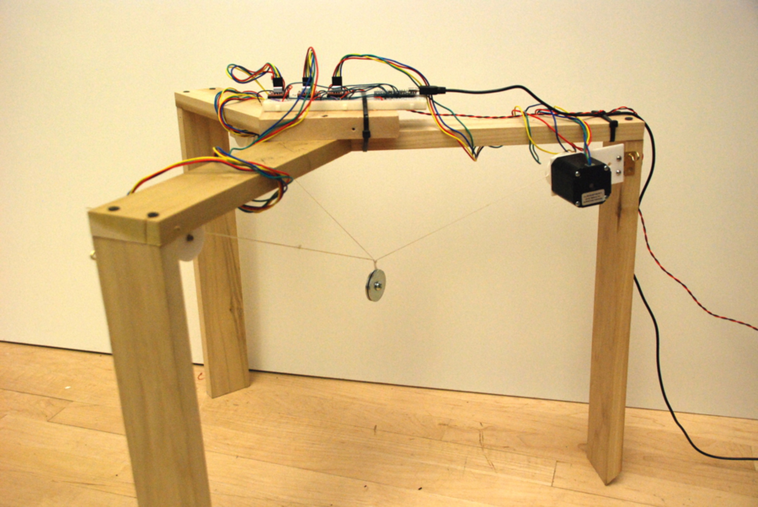
The inverse kinematics for moving the three motors into the right positions isn't as hard as I originally suspected it would be. The operation of the cable-driven system can be conceptualized simply as three line segments of different lengths, each connecting the lightbulb to one of the motors. 

The question is, Given a particular lightbulb destination position, what position should the motors rotate to? Reformulated, the question really is, How far is it from the desired lightbulb position to each of the three motors? It turns out that this is an especially easy question to answer.

To find the distance between any two points, in a vector system of any dimensional cardinality, simply apply the distance formula! In a 2D cartesian plane, this is familiar from 8th grade:

 D = sqrt( (x1 - x2)^2 + (y1 - y2)^2 ).

In words, the distance between two points is the square root of the x difference squared plus the y difference squared. So: how far apart is the point (8, 4) from (13, 12)? It's sqrt( (8-13)^2 + (4-12)^2 ), or ~9.4. 

How does this generalize into three-dimensional space? Very simply!

 D = sqrt( (x1 - x2)^2 + (y1 - y2)^2 + (z1 - z2)^2 ).

Just add the z term. For instance, what's the distance from the point (8, 4, 3) to (13, 12, -5)? It's sqrt( (8-13)^2 + (4-12)^2 + (3 + 5)^2 ), which is ~12.4. No matter how many dimensions you're doing math in, you can find the distance between two points like this.

The function below, threespaceToTriangle, takes three arguments which are the x, y, and z coordinates of the desired lightbulb position, and uses the 3D distance formula to calculate the appropriate motor position for all three motors. It's got the motor positions baked in as the starting point, and uses the input values as the other point to measure distance to. (It loads the resulting values into a previously declared array, tri[], because unfortunately C functions cannot return multiple values. You can get around this with referencing and dereferencing, or using structs, but I wanted to keep it simple.)

Note that the coordinate system I built is structured so that the definition of one unit is the distance from the center of the top planar triangle (between the motors) to one of the vertices.

Show Advanced Options

Prototyping rig

Prior to installing the final system in the exhibition space, I tested the motion math, as well as the motor control system, by building a small three-sided testing rig. I installed the motors and spools, and moved a small weight around to see if I could successfully control its positioning. It was buggy at first; I confused motors for each other in code, plugged in steppers backwards so they ran the wrong way, and I had to empirically find how many steps were needed for a motor to move one "unit." But building this rig was very helpful and basically once I'd validated the math, I was able to move the small weight to pretty much any position inside the reasonable motion envelope of the equilateral triangle the motors were arranged in.

Dsc 0078.jpg.thumb
Show Advanced Options
Dsc 0076.jpg.thumb
Show Advanced Options

Further work

Given more time to elaborate the project further, I have a few particular problems I'd focus on next:

1) Establish a sequenced calibration procedure. I did all calibration by hand, comparing Kinect data with manually entered motor positions. This was laborious, slow, and probably less precise than building a calibration sequence into the software would be.

2) Debug motor speed. In my experience, the fewer stepper motors the Arduino is running, the faster they will run. So even if the Arduino is issuing instructions to three steppers to all run at 1000 steps/second, these will run noticeably slower than if it's issuing the same instruction at the same target speed to only one stepper. I'm not sure if this is a flaw in the AccelStepper library, or my implementation, or something else altogether, but it's very vexing and led to some unwanted unevenness in output motion. I'd like to squash this bug once and for all because it causes a lot of trouble!

3) More careful matrix transformations. I noticed what appeared to be some nonlinearity in the Kinect data I was gathering. That's manageable if multiple data points are collected and a new correcting function is built based on these known data points. Then the corrected data could be fed into the motor instructions, increasing the efficacy of the matrix transformation and the output accuracy.

4) Perhaps the best calibration procedure possible would be one where the Arduino moves the lightbulb to specified positions, and where the Kinect (which has an IR camera after all) would note the lightbulb position by looking for its heat signature. That would require some elementary computer vision processing on the raw input data. If it worked, this would be a calibration that needs no human model involved and would allow for automatic high-precision alignment of the two matrices.

Drop files here or click to select

You can upload files of up to 20MB using this form.