Process
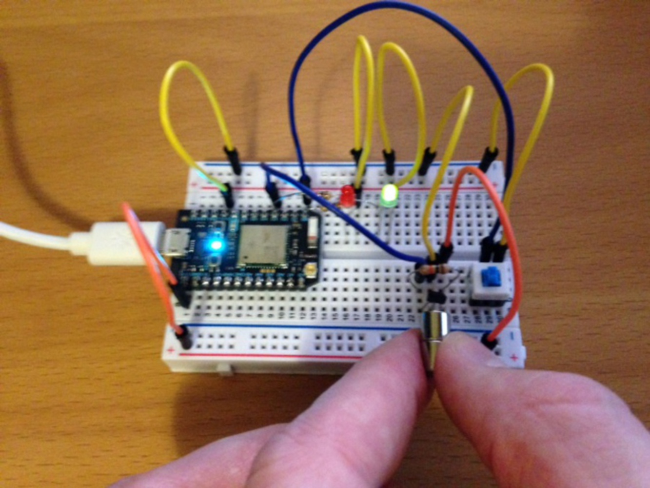
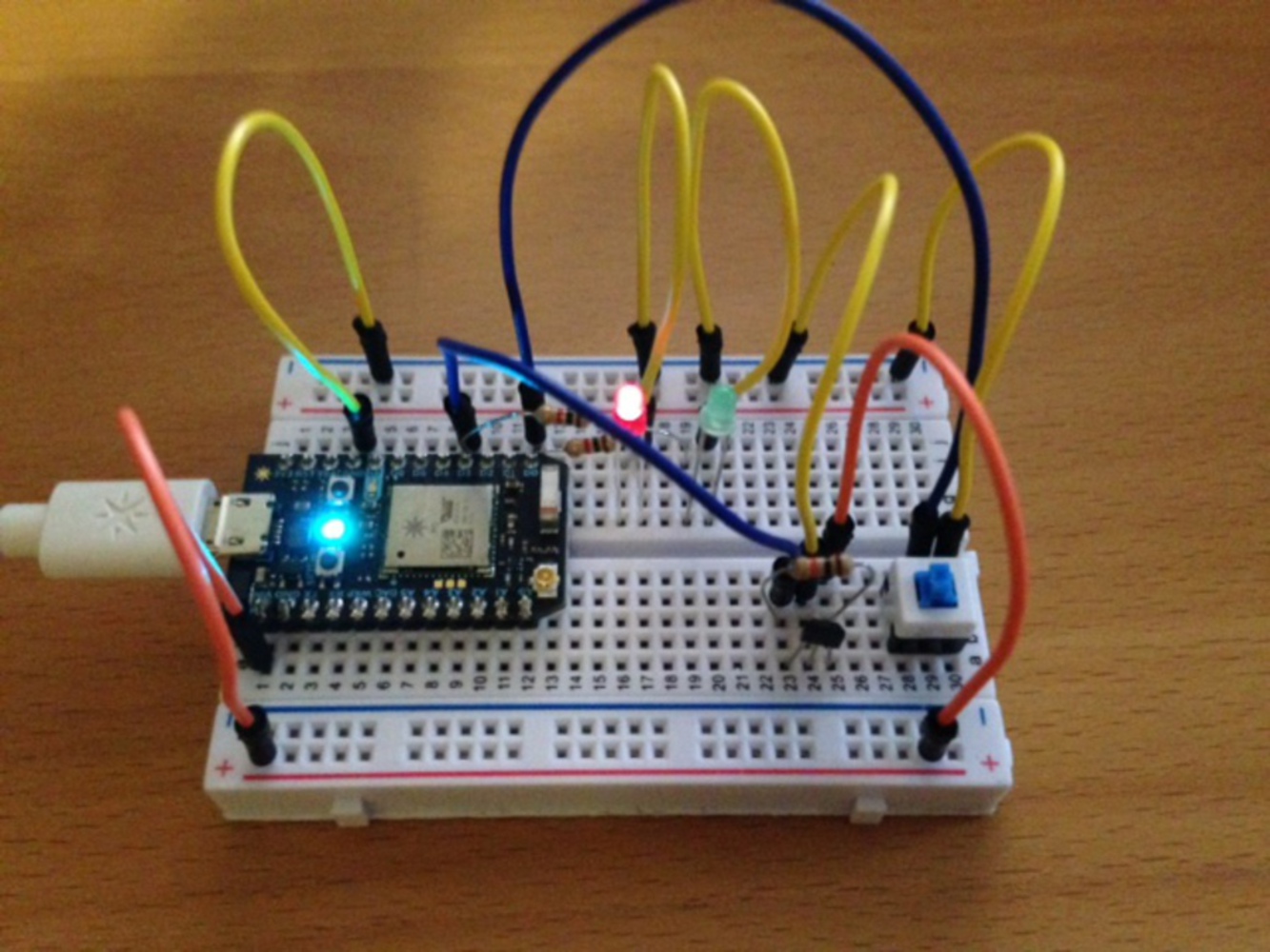
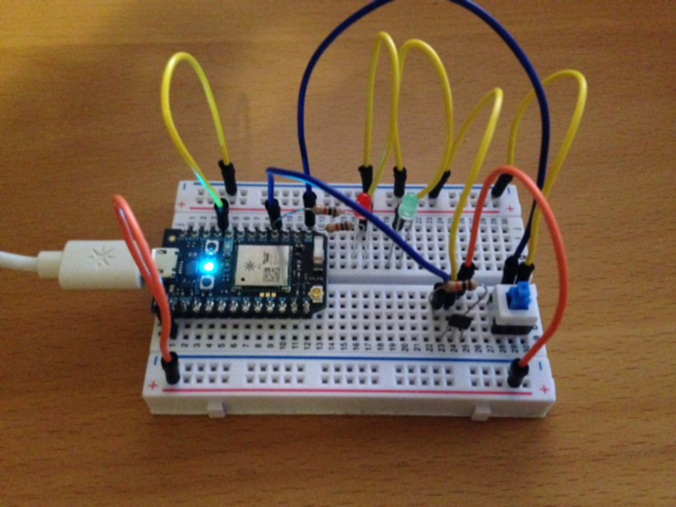
I assembled the circuit step by step, testing each component as I moved along. First, I installed the red and green LED lights, connecting them to ground and a digital input / output node. I then wrote a test code to ensure each LED functioned properly. Next, I installed the on / off switch, also connecting it to ground and a digital input / output node. I then progressed the code, testing the on / off capabilities by connecting the button to the red and green LEDs. When I depressed the button, the green light turned on, and when I released the button, the red light turned on.
After installing the button and the LEDs, I assembled the Hall Effect sensor. This required connections to power, ground, and a digital input / output node. A resistor between power and the digital feed helped indicate when the unit was activated and deactivated (via a magnet). After this, I changed the code so the Hall Effect sensor would change the LED outputs when activated / deactivated. I also connected a variable value to the cloud to indicate when a magnet was present / not present so IFTTT could push a notification to the user.
Finally, I changed the code slightly so the button activated / deactivated the code running the LEDs, the Hall Effect sensor, and the cloud variable (via a simple if statement). After this, I tested the on / off functionality, the LED lights (green = magnet present; red = magnet not present), and the push notifications. IFTTT is somewhat slow to read the variable (i.e., it's not immediate), so a notification takes approximately 30 seconds – 1 minute.
Code Sources:
http://daraghbyrne.github.io/diotlabs/1-a-simple-internet-appliance/first-sketch/
http://daraghbyrne.github.io/diotlabs/5-getting-input/buttons/
http://garagelab.com/profiles/blogs/tutorial-how-to-use-the-hall-effect-sensor-with-arduino


