Back to Parent

Outcome


Goal

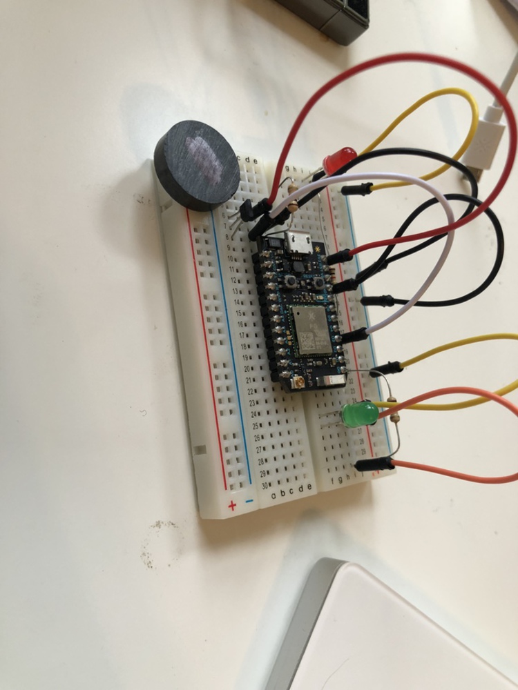
My goal in this project was to give my brother the ability to setup some basic monitoring of his room access while he wasn't at home. Since his room does not have a lock, I thought this would be a way for him to be able to keep a record of how many times someone entered his room while not at home. My solution addresses this problem in the way that it is able to provide glanceable information on the fundamentals, i.e., did someone enter my room or not?, and gives more detailed records over email, made possible by IFTTT. 
Process & Outcome

I initially began by thinking I would use an RGB LED, a button, a hall effect sensor & IFTTT for my needs. Using a HE sensor, I would monitor the door, and based on the signal coming, I would check whether the door was open or not. Based on whether the door had been opened since the last reset - the RGB LED would turn either red or green whenever the button was pressed, say as my brother walked into his bedroom after  getting home - and IFTTT would send him an email every time someone opened his door. 


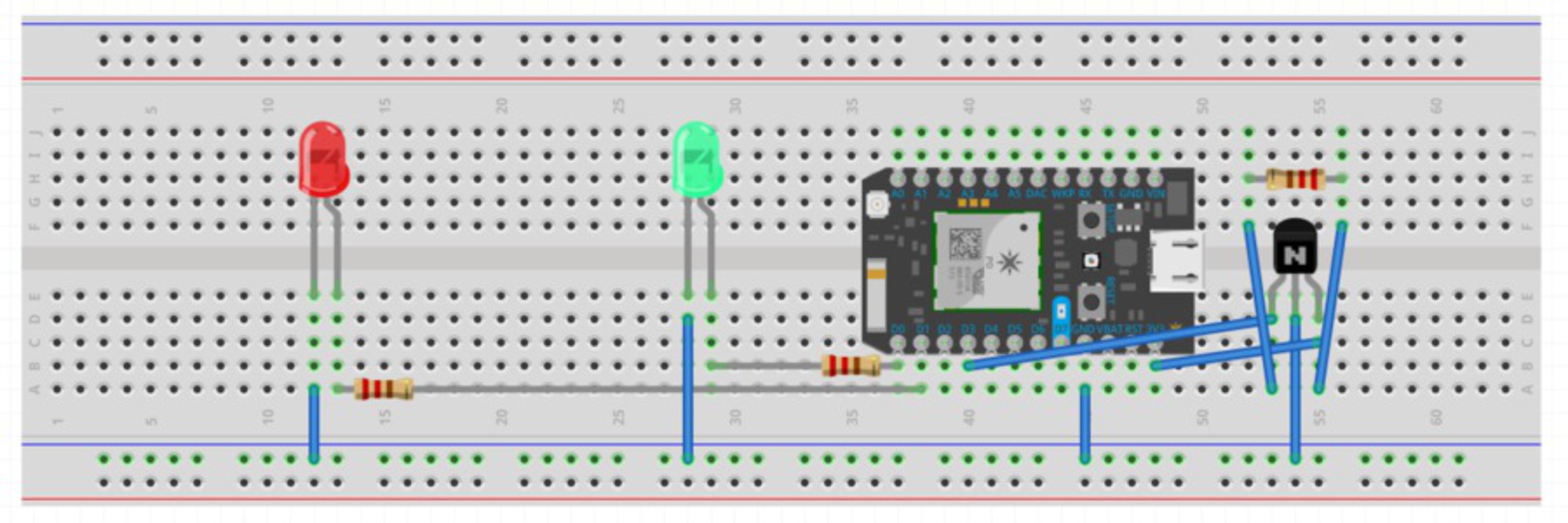
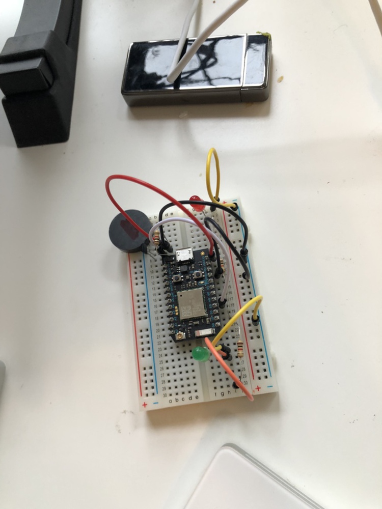
Unfortunately, as I worked through the process, I ran into issues regarding 1. the RGB LED - I was unable to power it properly, and 2. the button, which I was unable to make play properly with the Hall Effect Sensor. As such, I ended up getting switching the RGB LED with 1 green and 1 red LED instead, and removed the button altogether, letting one of the 2 LEDs remain turned on in perpetuity. 

My next goals would be to implement it on the door itself, and build in the button. 

Bill of Materials

1x Particle Photon 

1x Red LED 

1x Green LED 

3x Resistors

Jumper Cables 

Breadboard

Hall Effect Sensor (US5881)

Magnet

Reflection & Links

Never having worked with electronics before, my biggest challenge in this project was understanding how everything worked together - the learning curve in this regards. If I performed another iteration of this project, I would use more sensors to get a more accurate picture if someone entered the room - maybe using light or proximity sensors of some kind. I would also try and bring the 2 LEDs to one by switching to an RGB LED - I can also use this to provide a more granular look at the data, maybe different colors/shades of colors to indicate the severity of the breach. 


I used the link below to help me with the coding for the Hall Effect Sensor 

https://maker.pro/education/a-simple-guide-to-using-a-hall-effect-sensor-with-arduino/

Show Advanced Options
Img 0359.thumb
Show Advanced Options
Img 0358.thumb
Show Advanced Options
Screen shot 2018 02 06 at 11.33.33 am.thumb
Show Advanced Options

I used a different part which looked similar and had the same number & patterning of pins, instead of a Hall Effect Sensor on the breadboard diagram since I couldn't find the exact part on Fritzing. 

Drop files here or click to select

You can upload files of up to 20MB using this form.