Back to Parent

Outcome


Intention

My goal is to create a pair of electric socks which can heat the user’s feet. I am proposing this as I have been quite fascinated by the idea of the electric blankets and I have been thinking about something similar designed just for the feet. Personally, I have always felt a need of something that warms my feet while I sleep – yes, blankets and normal socks don’t help :). The pair of socks would run by a rechargeable battery and could provide adequate amount heat to the feet as the user deems comfortable.

Process

The process is divided into the following steps:

1. Background Research:

I conceptualized the product as a derivative of the electric blanket. Electric blankets have been quite successful, and their 2017 market value is estimated to be around $300 Million [1]. Electric blankets have two layers with a resistive hating coil sandwiched between those two. The heating coil is operated by a temperature control panel connected to a power source.

2. Sketching the product

a. Sketching the coil placement:

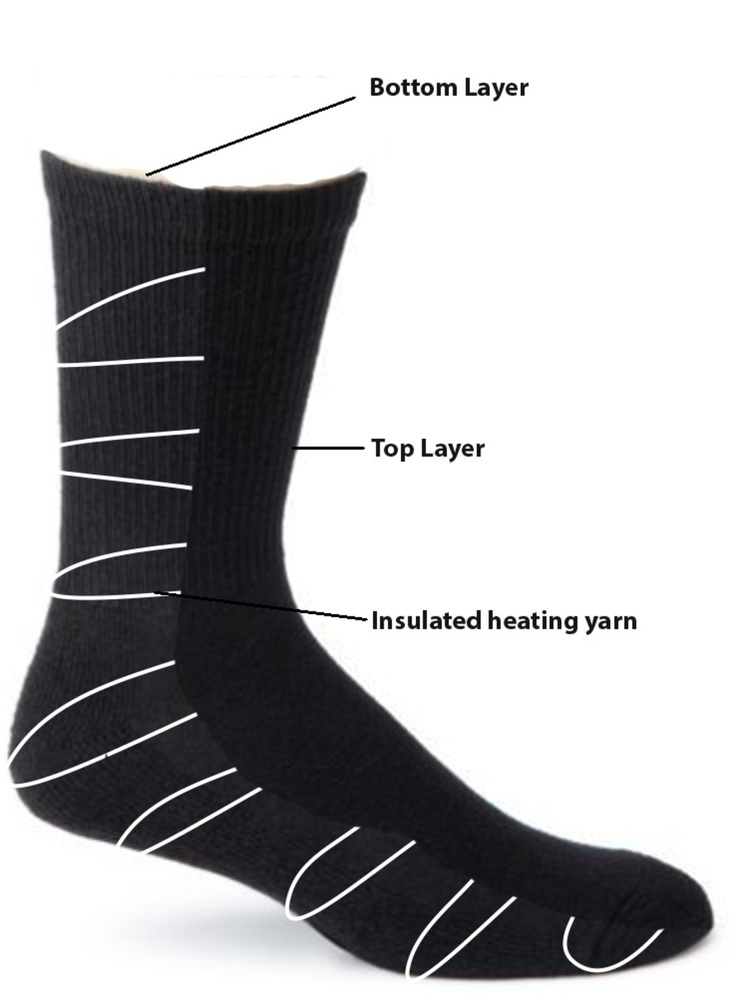
Picking the idea from the electric blanket, I propose to use insulated heating yarns sandwiched between two layers of the socks. The Figure 4 below shows a diagrammatic representation of the placement of the heating yarn. An example of the insulated heating yarn could be: THERMOTECH I-4.6 - Insulated Heating Yarn (4.6Ω/m)[2].

b. Ideas to place battery and temperature control panel

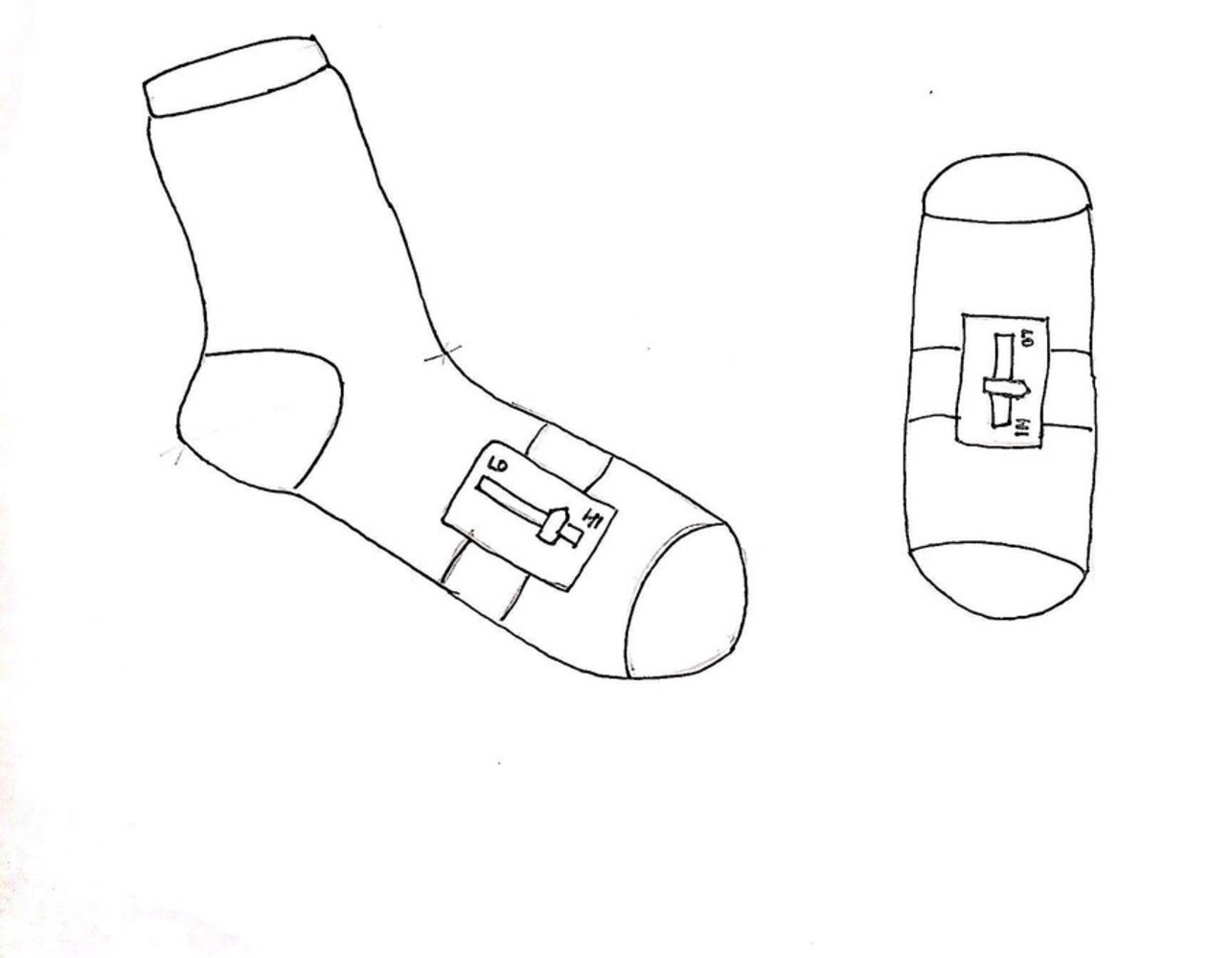
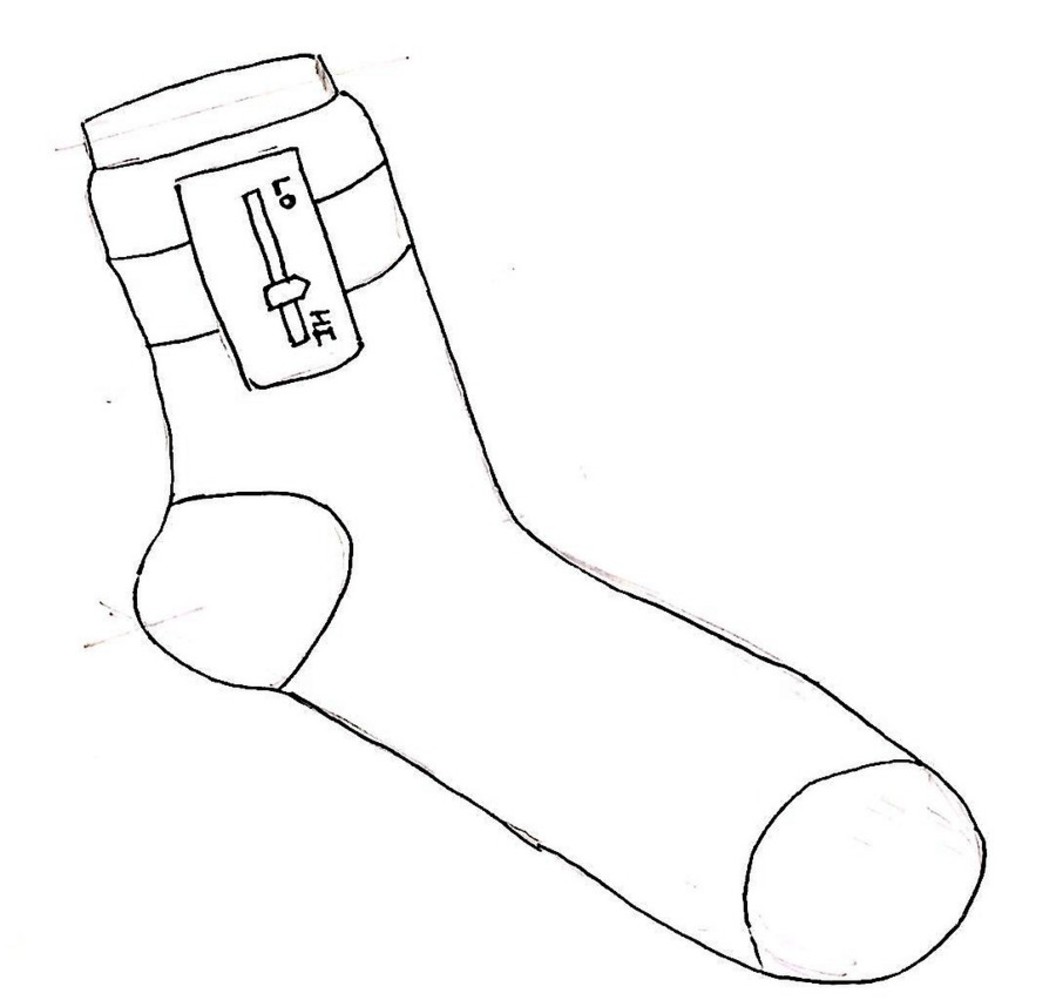
I brainstormed two possible locations to place the temperature control and the battery panel on the socks. In both the ideas the panels would be clung to the socks using a band and snap buttons.

i. Option 1 – Between calf and shin

The temperature control panel which also contains the battery could be strapped on with help of a band and snap buttons. Figure 1 shows the schematic placement of the panel on the sock.

1. Advantages – Comfortable position to be placed and the panel remains easily accessible

2. Disadvantages - Moves while one sleeps.
Img 4118.jpg.thumb
Show Advanced Options

ii. Option 2 – On the bottom of the sock

The could also be strapped on with help of a band and snap buttons on the bottom of the sock. Figure 2 shows the schematic placement of the panel.

1. Advantages – Comfortable while sleeping

2. Disadvantages – Not easily accessible

Img 4119.jpg.thumb
Show Advanced Options

3. Circuit

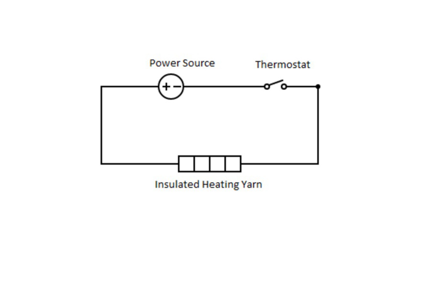
The basic circuit diagram for the socks would be:

Circuit.thumb
Show Advanced Options

4. Materials

a. Conductive yarn – To create a closed electric circuit between the power source and the heater

b. Insulated heating yarn – To produce heat of desired intensity

c. Strap on battery and temperature control panel – Battery would enable the heater to generate heat through electric current. A temperature control unit would vary the resistance in the electric circuit to control the heat and map it to the desired intensity. It would also cut-off the current supply to maintain the desired temperature.

5. Socks manufacturing

As depicted in the Figure 4 below, a knitting machine would be used to create two different layers of the sock which would sandwich the insulated heating yarn. The insulated heating yarn would be stitched to the base layer. The female part of the snap button could be stitched on the top layer using a conducting yarn, connecting the insulated heating yarn below. The band of the temperature control panel would have the male part of the snap button stitched through the conductive yarn. Closing the snap buttons would complete the circuit to enable the flow of current.

Crosssection.jpg.thumb
Show Advanced Options

Reflection 

Looking at the concepts I have used in my projects, I am amazed at my learning curve in this micro course. Given my father is a textile engineer, I learnt a lot about textiles and the manufacturing units very early on in my life. I am very surprised about the fact that I got to learn a new thing in each of the three classes. One of the most interesting topics was the conductive textile materials and hence I tried to explore its application in my project. I am now looking forward to utilizing the techniques learnt in the class on more projects. 

Img 4132.jpg.thumb
Show Advanced Options
Img 4131.jpg.thumb
Show Advanced Options
Img 4128.jpg.thumb
Show Advanced Options
Img 4130.jpg.thumb
Show Advanced Options
Img 4129.jpg.thumb
Show Advanced Options
Img 4133.jpg.thumb
Show Advanced Options
Img 4134.jpg.thumb
Show Advanced Options
Img 4135.jpg.thumb
Show Advanced Options
Drop files here or click to select

You can upload files of up to 20MB using this form.