Back to Parent

Outcome


Research & Context

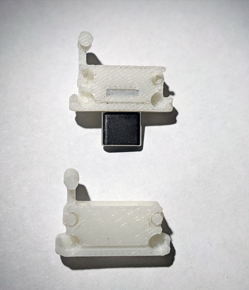
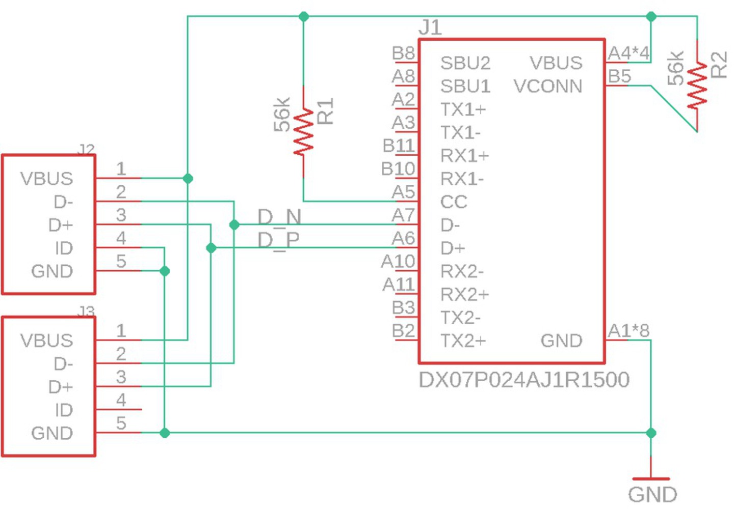
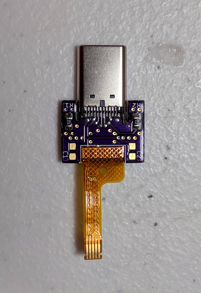
Although the ultimate functionality of the assembly is the same, usage of a USB type-C connector for compatibility with newer smartphones is new. In fact, Seek themselves do not produce a smartphone thermal camera with a type-C connector.

Aesthetic Inspiration

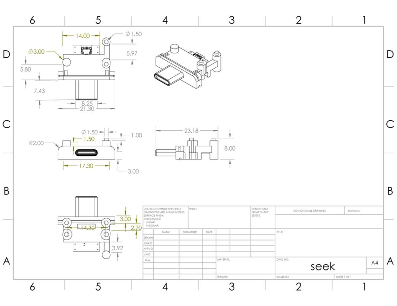
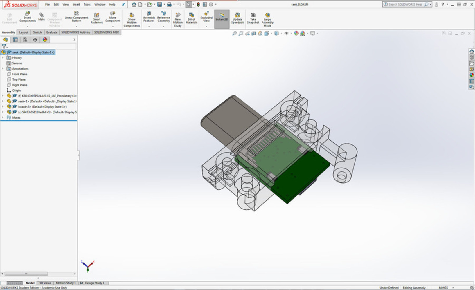
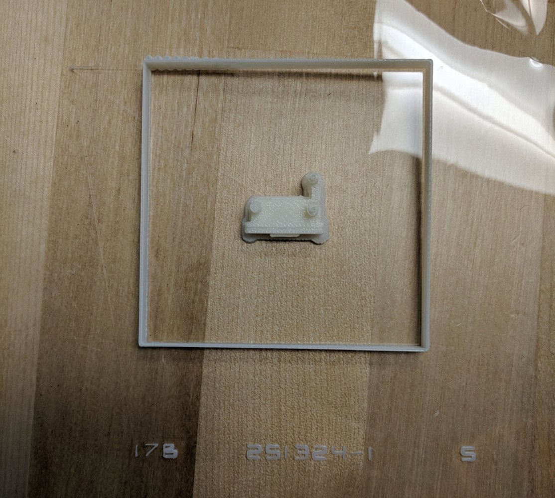
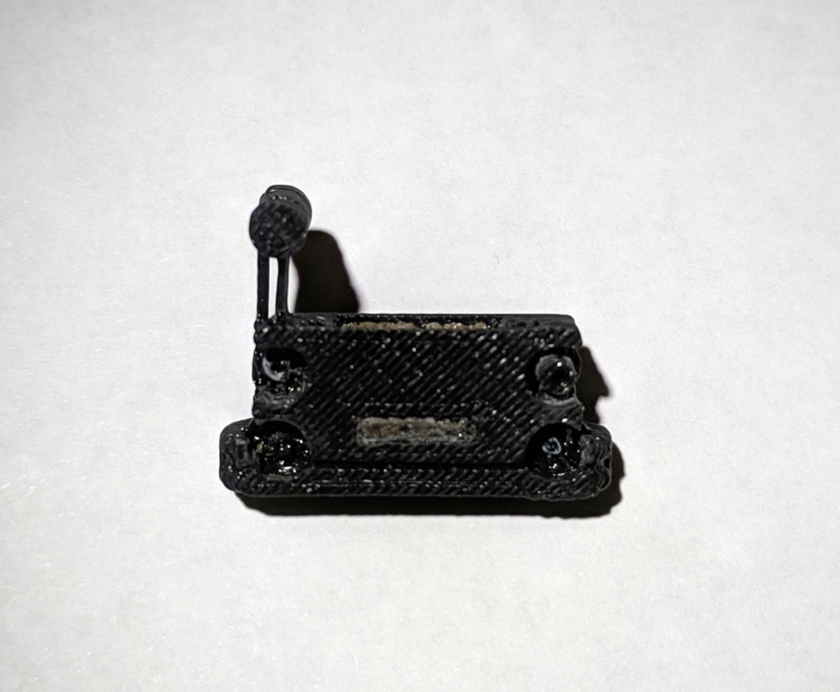
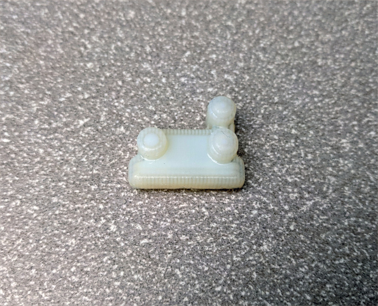
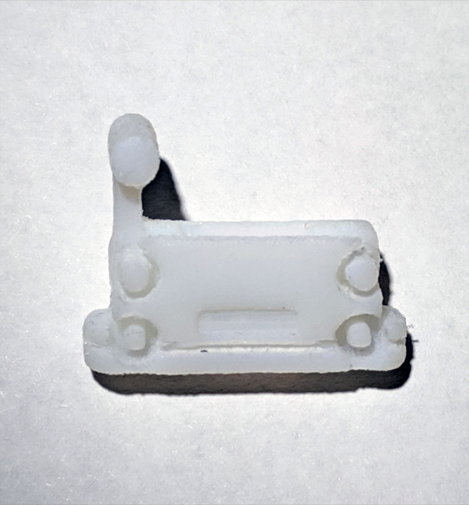
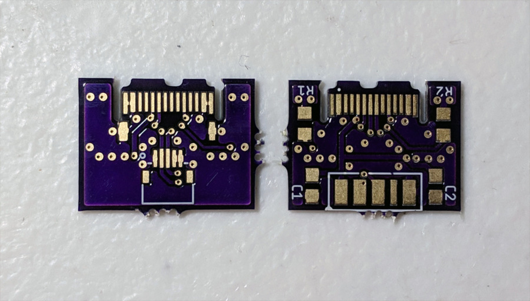
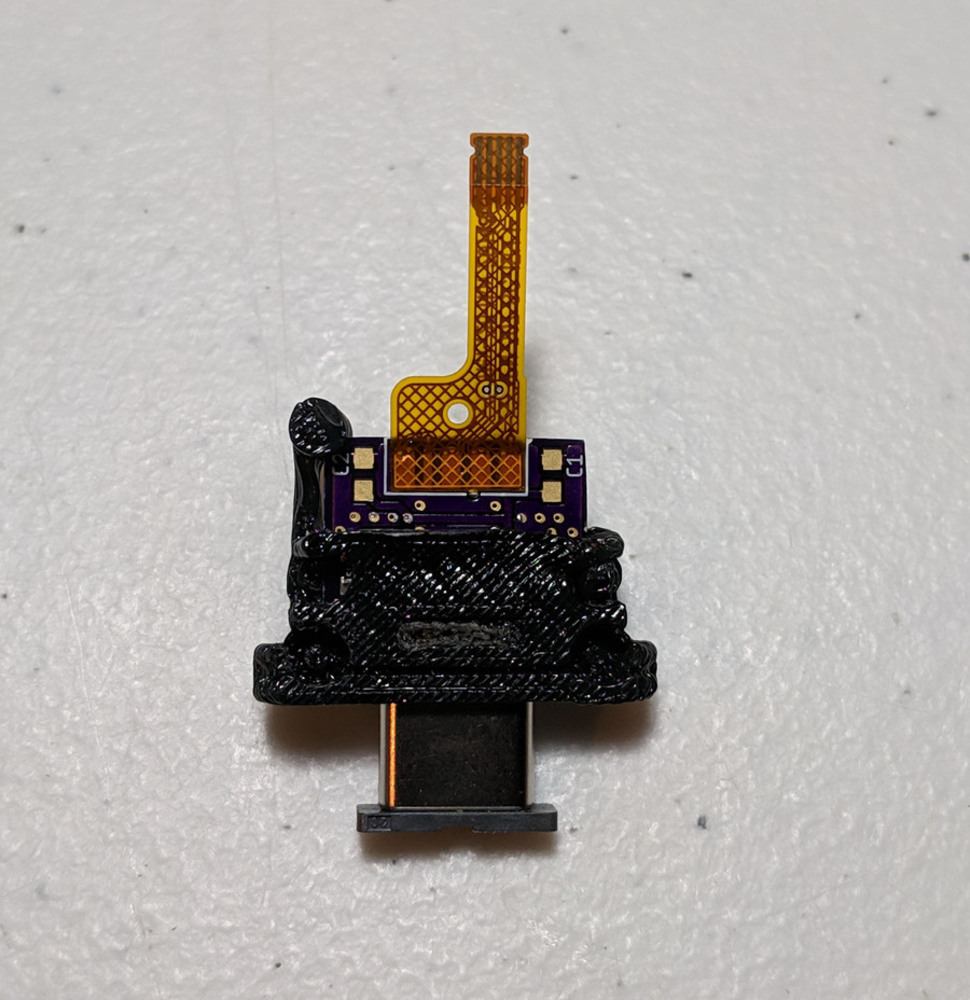
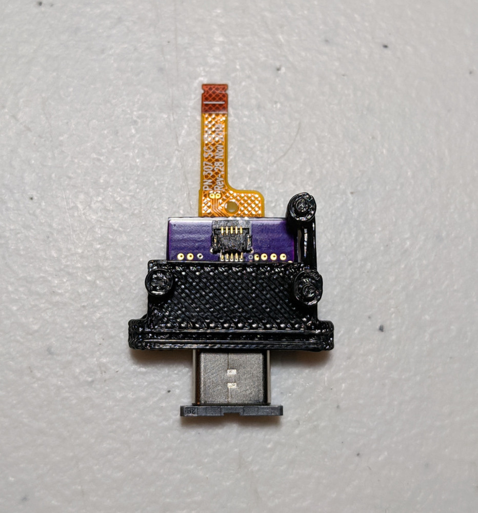
The design of the replacement assembly is very minimalist, focusing on functionality while matching the original dimensions. Nevertheless, a symmetrical design with beveled edges produces an appealing aesthetic. 

Project Sketch

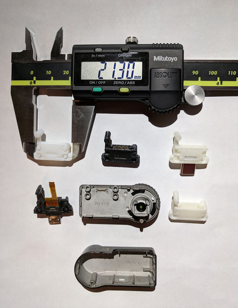
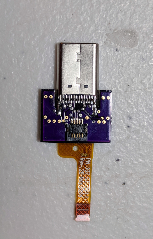
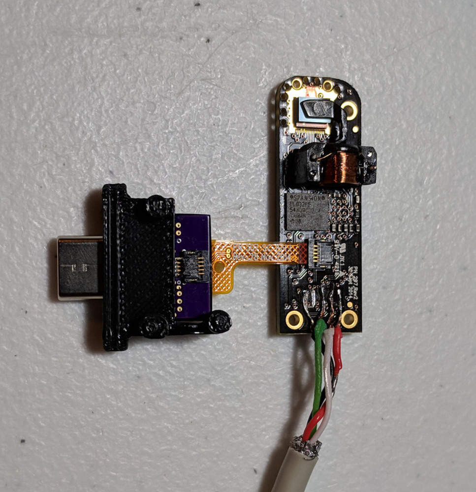
Developing the project sketch involved measuring the dimensions of the original connector assembly, and that of the shell pieces that encase the connector assembly. This process involved multiple iterations with a caliper, as offsets or mistakes of as little as 0.5mm would result in incompatibility.

Seek.jpg.thumb
Show Advanced Options

Process & Procedure

After measuring determining the dimensions of the original assembly, I modeled a replacement with a type-C USB connector in SolidWorks. Maintaining the original placement of the mounting pins ensures compatibility with the original case and main circuit board. This involved drawing the front face, the cutout for the type-C connector, the left and right supports, followed by the posts and top/bottom mounting pins, plus beveling, extruding, and cutting, where appropriate. Finally, a cutout was added for the circuit board to slide into.

Next, I designed a circuit board that interfaces between the type-C USB connector, and the flat flex cable (FFC) that connects to the main circuit board, using Autodesk EAGLE. This is necessary because although the type-C USB connector is electrically backwards-compatible with the original micro-B USB connector, additional components are required to signal USB 2.0 operation mode, instead of USB 3.0/3.1 operation mode, which uses additional signals and pins on the type-C connector.

Subsequently, I exported a 3D model of the circuit board from EAGLE, and imported it as a part into my connector assembly using SolidWorks CircuitWorks. Likewise, I also imported manufacturer models for the type-C USB connector and FFC connector. This allowed me to verify that my CAD model is consistent, without interference between sub-components.

Solidworks.thumb
Show Advanced Options

Document & Reflection

Mechanical

Multiple iterations of modeling and printing were required before correct positioning of the mounting pins and cutouts was determined. This process was made more difficult by variations in tolerance, material strength, infill percentage, and support material, between various 3D printers. Initial prints were made using the Stratasys Continuous Build (shown below) in IDeATe, but the resulting part was fairly brittle, and structurally weak. In particular, the circular mounting pins were damage-prone while removing support material.

Stratasys.continuous.build.1.thumb
Show Advanced Options
Stratasys.continuous.build.2.thumb
Show Advanced Options

Subsequent prints were made on the Stratasys Dimension Elite (shown below, black) and Stratasys Objet30 (shown below, white) in Tech Spark, which generally turned out better, but still broke occasionally.  

Stratasys.dimension.elite.thumb
Show Advanced Options
Stratasys.objet30.1.thumb
Show Advanced Options
Stratasys.objet30.2.thumb
Show Advanced Options

Below is a composite image, showing the original  damaged mini-B USB connector, interior of the shell pieces, various prints of the type-C replacement, and length measurement using a caliper.

Composite.thumb
Show Advanced Options

Electrical

Designing the interface circuit board involved reading through the USB Type-C Connector Specification, published by the USB-IF, which details how the reversible connector is implemented electrically, and gives appropriate values for the pullup/pulldown signaling resistors. After developing the appropriate schematic, parts for the type-C connector and the FFC connector were selected and sourced, and footprints were created in EAGLE for board layout. As an alternative to the FFC connector, a separate surface-mount footprint for the original flat flex cable from the mini-B USB connector was added, if available for reuse. Shown below are the schematic and layout, as well as photos of the assembly process.

Electrical.schematic.thumb
Show Advanced Options
Electrical.board.thumb
Show Advanced Options
Board.thumb
Show Advanced Options
Board.bottom.thumb
Show Advanced Options
Board.top.thumb
Show Advanced Options

Finished Project

Shown below are photos of the completed assembly. However, due to a mistake made in the schematic, another board revision needs to be produced for correct electrical connectivity. Likewise, due to structural integrity and tolerance issues with the current 3D printed assembly, a final version will likely need to be produced through Shapeways, a third-party 3D printing company.

Final.top.thumb
Show Advanced Options
Final.bottom.thumb
Show Advanced Options
Final.connected.thumb
Show Advanced Options
Drop files here or click to select

You can upload files of up to 20MB using this form.