Back to Parent

Outcome


Using a pushbutton

  Turn a light on and off using a pushbutton.  

1.pushbotton.thumb
Show Advanced Options

Using a switch

Turning light on and off through a switch.

The code is the same as the pushbutton.

2.switch.thumb
Show Advanced Options

Using a potentiometer

  Fade up and down an LED as you turn the dial.

3.potentiometer.thumb
Show Advanced Options

Combining a switch and potentiometer

The switch should turn on and off the light while the potentiometer will fade up and down the light (but only when its on).

4.switchandpotentiometer exercise 1.thumb
Show Advanced Options

Using a photoresistor

The program shows how much light is available. When there is lots of light the LED is bright. When there is little light it’s dim.  

5.photoresistor.thumb
Show Advanced Options

Exercise 1:

Modify the program so that the LED shows the opposite. When there is little light, it will be bright and when there’s lots of light, it will be off.

Show Advanced Options

Exercise 2:

Turn the light on and off when reaches certain levels. If the light levels are below 600 turn the light on (and bright), otherwise turn it off.  

Show Advanced Options

Practice Exercise: 

Combining Sensors and Inputs 

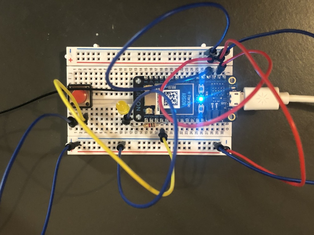
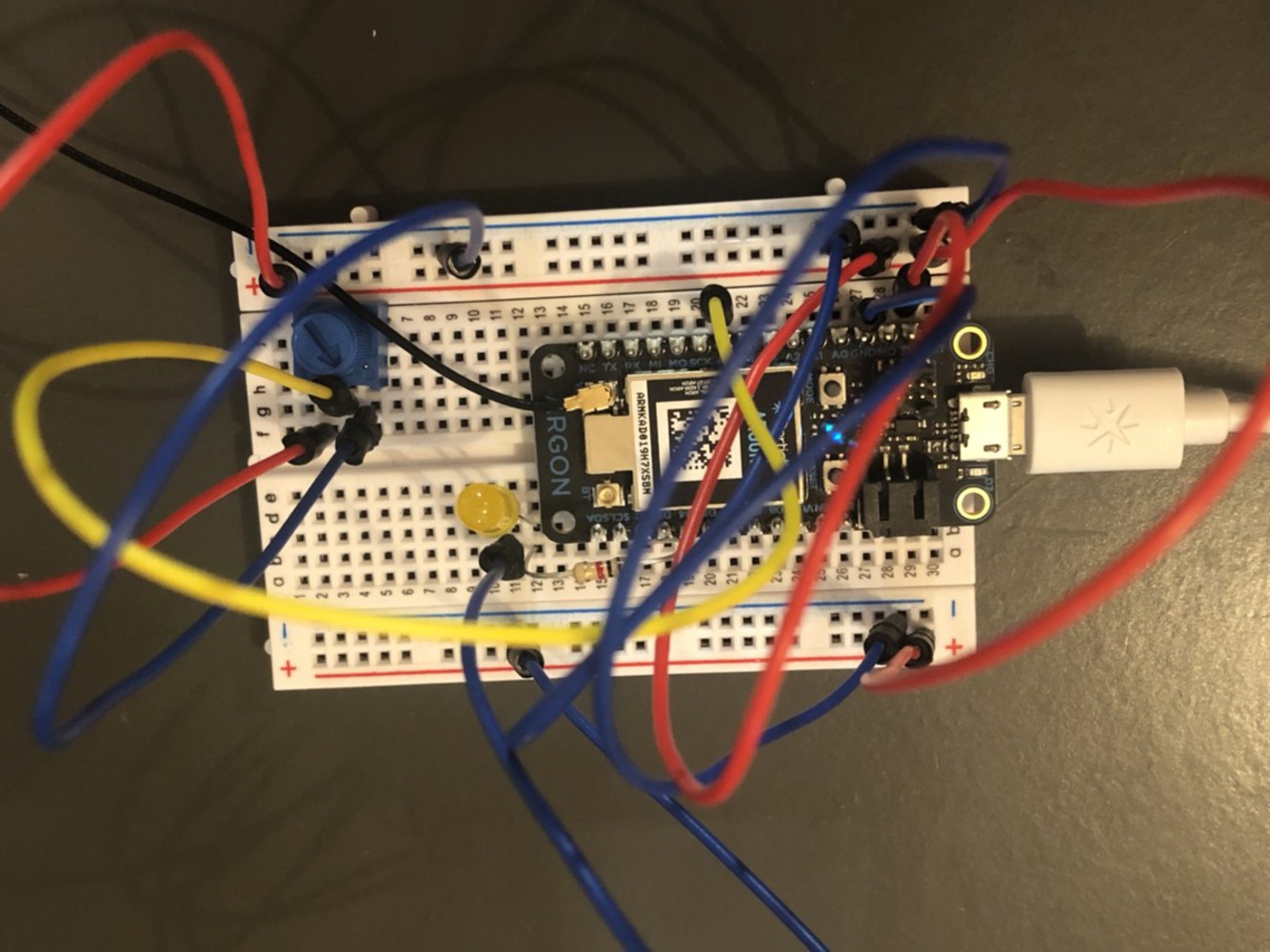
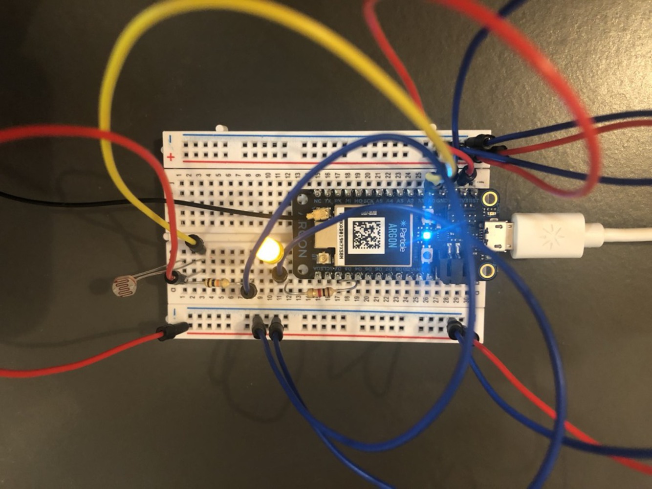
In this exercise, I used a switch, photoresistor, and LED. The switch is controls the overall action of the LED light. LED and phtoresistor will only respond if the switch is switched on.

The scenario is for work lamp, which brightens up and dims down according to the existing light level in the room or daylight. But it will only work when the switch is on.

8.combineseonsorsandinputs.thumb
Show Advanced Options

Process & Reflections

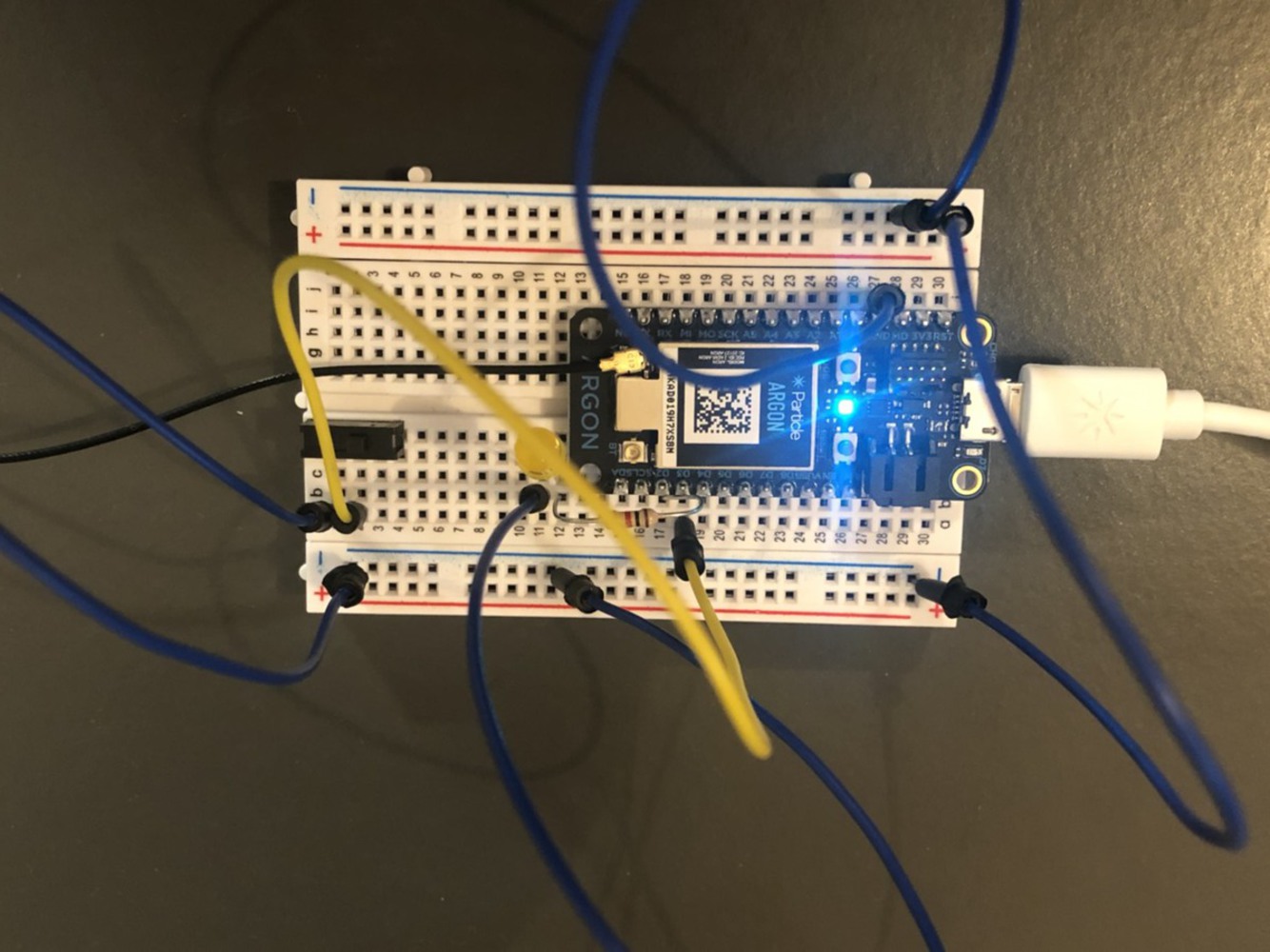
I started out with one input or sensor one a time, and then add on to it another input. This helped me to understand how the circuit works on the breadboard. 

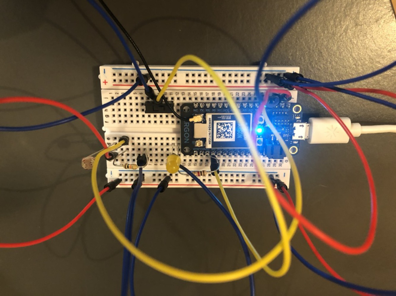
Relating the photoresistor reading value (0-4095) and the PWM range (0-255) to the actual brightness seen through human eyes, was an odd process for me. It took a few try outs to see what it actually looks like by trying out different values and checking the reading from Particle Console. The photoresistor sensor also seems a bit unstable with instances where LED brightness not reacting or reacting slowly.

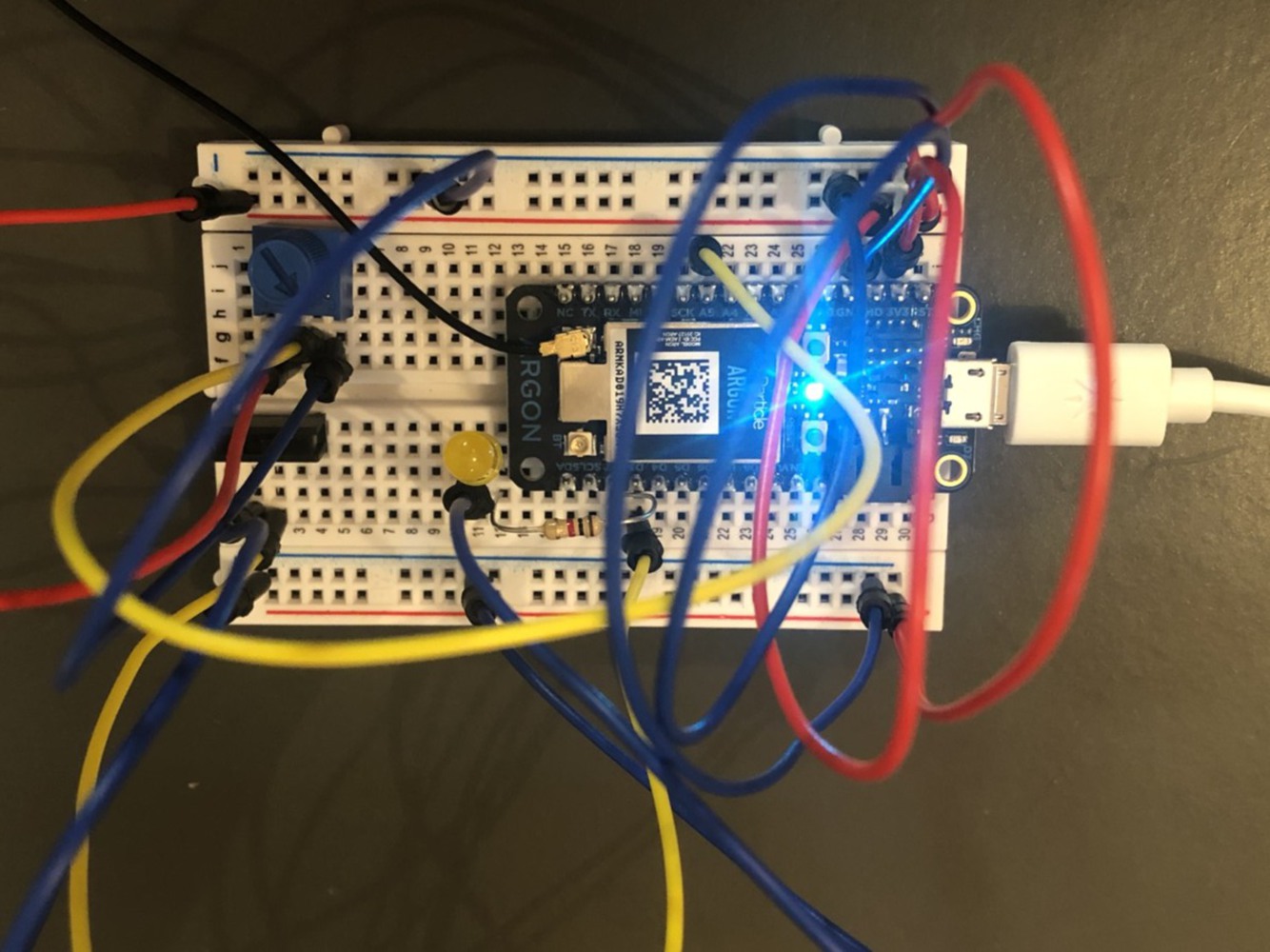
Overall, I think I gained better understanding in how the circuit works on the breadboard. And it was nice to imagine how the prototype relates to the real world.


Drop files here or click to select

You can upload files of up to 20MB using this form.