Back to Parent

Outcome


Img 20221103 193345.thumb
Show Advanced Options
Gif.thumb
Show Advanced Options

Outcome

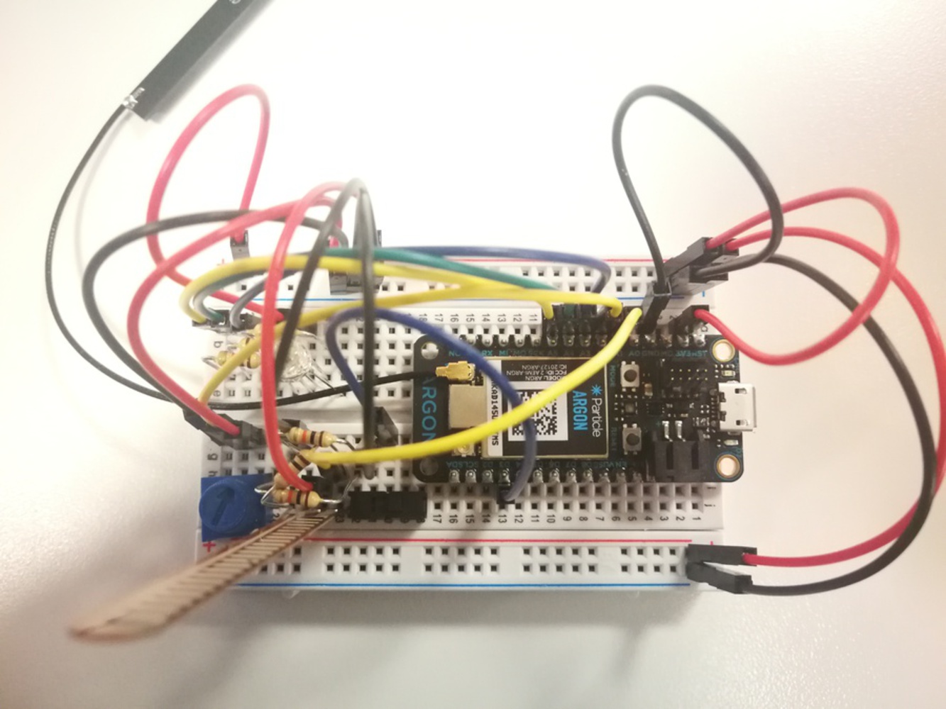
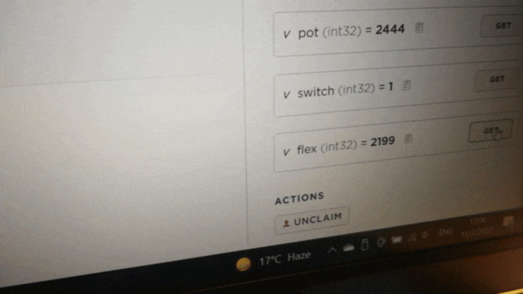
In this project, a switch, flex sensor, and potentiometer were used to control an RGB LED in different ways:

  • Turning the potentiometer controlled the intensity of the Red light coming from the LED. Further clockwise = more intensity.
  • Bending the flex sensor changed the intensity of the Blue light coming from the LED. More flex = more intensity.
  • Flipping the switch causes a digital pin pulled-up to read LO, and turns off the RGB LED no what the values being read from the potentiometer and flex sensor were. Left = OFF, Right = ON.
Show Advanced Options

Process

Reusing my code and wiring for the RGB LED from Skill Dev I, I decided to use the potentiometer and flex sensor as they both had variable resistance that could be mapped to PWM to control the intensity of the LED. Since neither sensor was ideal, I had to modify their expected analog ranges when mapping them to PWM to match their actual limits so that the LED would actually be able to turn fully OFF and ON. I also added a switch as I initially misread the prompt as requiring 3 sensors, and wanted to turn off the LED when I was modifying code without unplugging the board since the Argon is a little finicky about uploading code. In particular, every time I had to flash new code after plugging the board in, it would be stuck trying to connect to the cloud until I reset it after plugging it in for some reason.  

Reflection

While using the switch and potentiometer were straight forward, the flex sensor required a bit more work, including a voltage divider and some testing. Most tutorials suggested using somewhere between 10K and 100K of resistance in the voltage divider, so I went with 30K since our largest resistor was 10K and I didn't have too much space to stack more resistors in series. It seemed to work alright, but sometimes exhibited weird behaviors when unflexed, with its analog readout momentarily floating to a +-400 range sometimes. I suspect this is probably to do with the connection of the pins being kind of loose on the breadboard, and would probably switch to using an amphenol FCI clincher connector or solder lower gauge leads on if I were to use it for a project in the future.   

Drop files here or click to select

You can upload files of up to 20MB using this form.