Outcome
Process
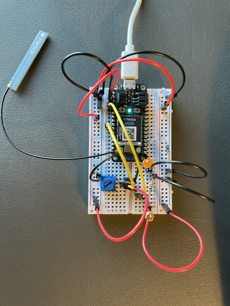
I first planned to use a temperature sensor for this project, but as I was setting up my circuit and reading about the sensors, I realized working with a temperature sensor during the second week of class might be more challenging, and that it might be harder to control the temperature as opposed to light to test my code and wiring. I therefore decided to switch to photoresistor. Wiring was not challenging, but it took me some time to get my code working, especially calibrating the photoresistor measurement and the potentiometer reading, and mapping out these values to see the effects on the LEDs I used.
Reflection
It was fun to connect two different sensors in this project. It was also exciting to see instant effect of running the code and testing if everything is working as intended. The photoresistor required some fine tuning, and at first I wasn't able to observe the effects of light or turning the potentiometer knob. It is therefore important to make sure your components work as intended before trying to complicate the code or the circuit.
You can upload files of up to 20MB using this form.