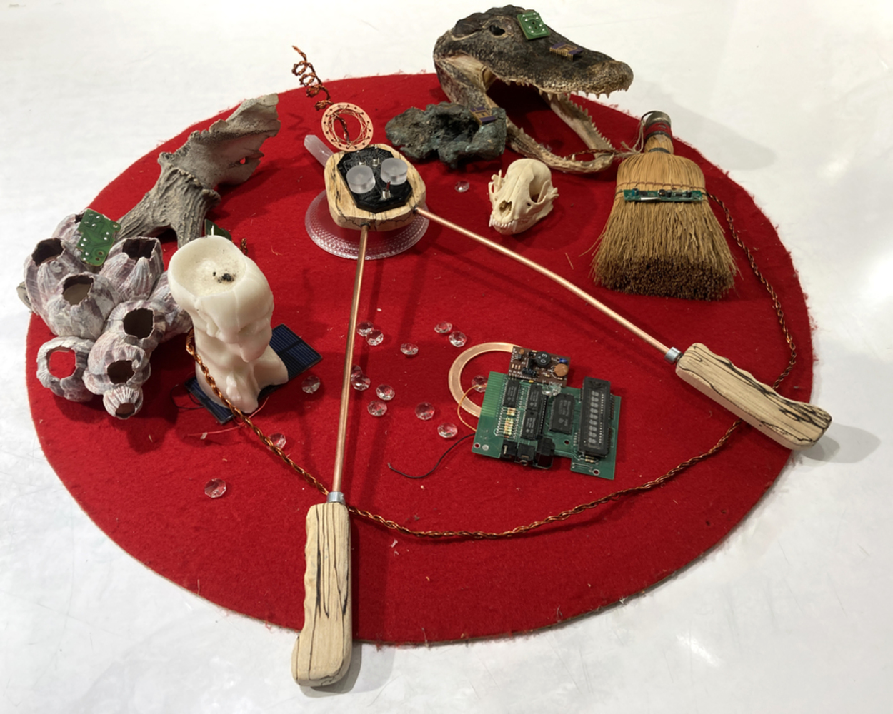
OUiFi- An EMF & Wireless Signal Dowsing Rod
Made by Phoebe
Made by Phoebe
A speculative design instrument that allows the user to feel the electromagnetic signals that are given off by power and wireless communications technology.
Created: December 1st, 2022
The OUIFi Dowsing Rod is a critical design project that explores the connections between wireless communication, the science (and pseudoscience) of electromagnetic fields and esoteric practices. Specifically, the instrument is a kind of dowsing stick - a "device" historically used to locate ground water, hidden resources or other sources of energy. Dowsing has also been used in more modern times by petrochemical companies and the military - complicating its status as a occult hoax. Conversely, electromagnetic waves used for radio, wifi, bluetooth and cellular transmission and other communication technologies present a form of energy imperceptible to humans yet are a foundation of modern communication. These signals have sometimes been the subject of conspiratorial speculation that sometimes leaks into the mainstream such as the debate around "5g" signals causing health issues, psychological damage or even transmittouing the covid-19 virus. The name "OUIFi" is a combination of Ouija
(pronounced "wee-jee") board, a "tool" for communicating with spirits, and "Wi-Fi".
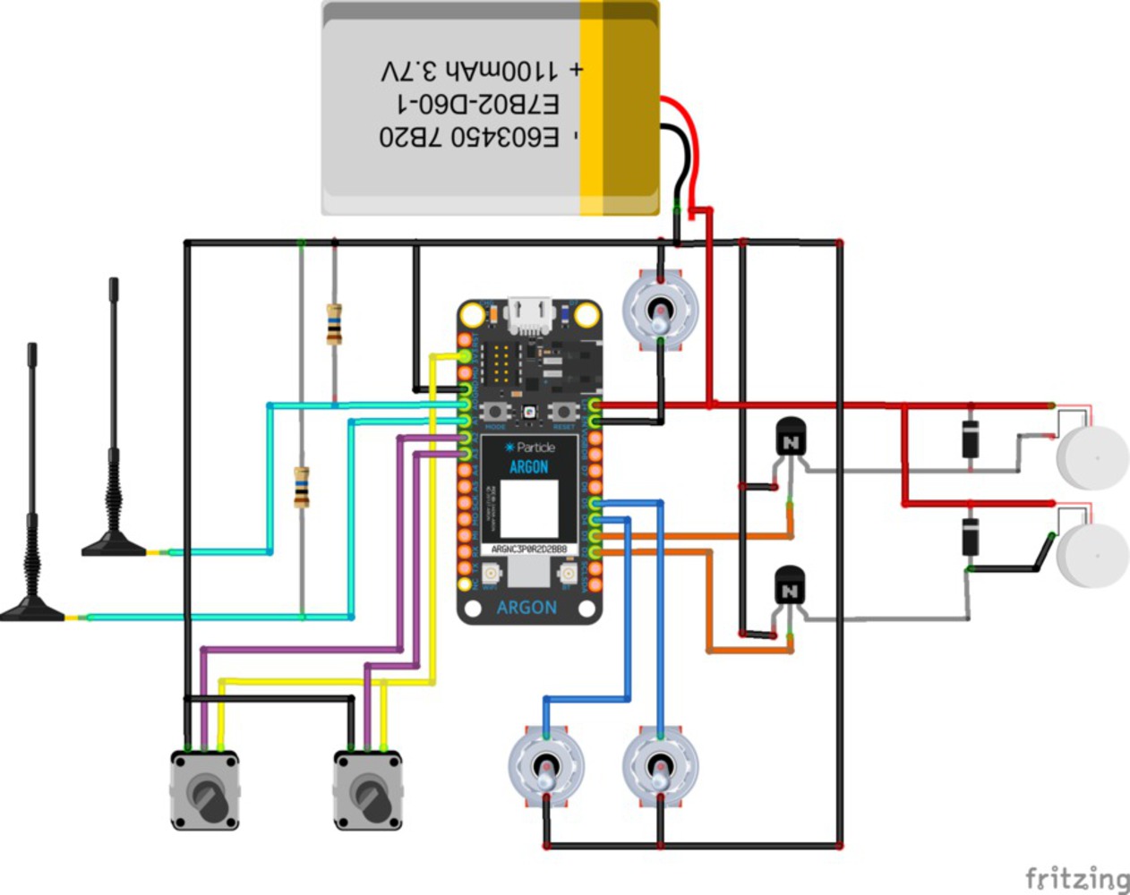
The instrument uses a Particle argon microcontroller equipped with antennas to measure the strength of electromagnetic fields (EMF) and wifi signals. The user holds the OUIFi dowser with the provided handles and in the presence of an electromagnetic field the handles will vibrate relative to the strength of the EMF. The device runs on a rechargeable LiPo battery making it entirely portable -allowing the user to explore their surroundings and discover different sources of EMF in their environment.
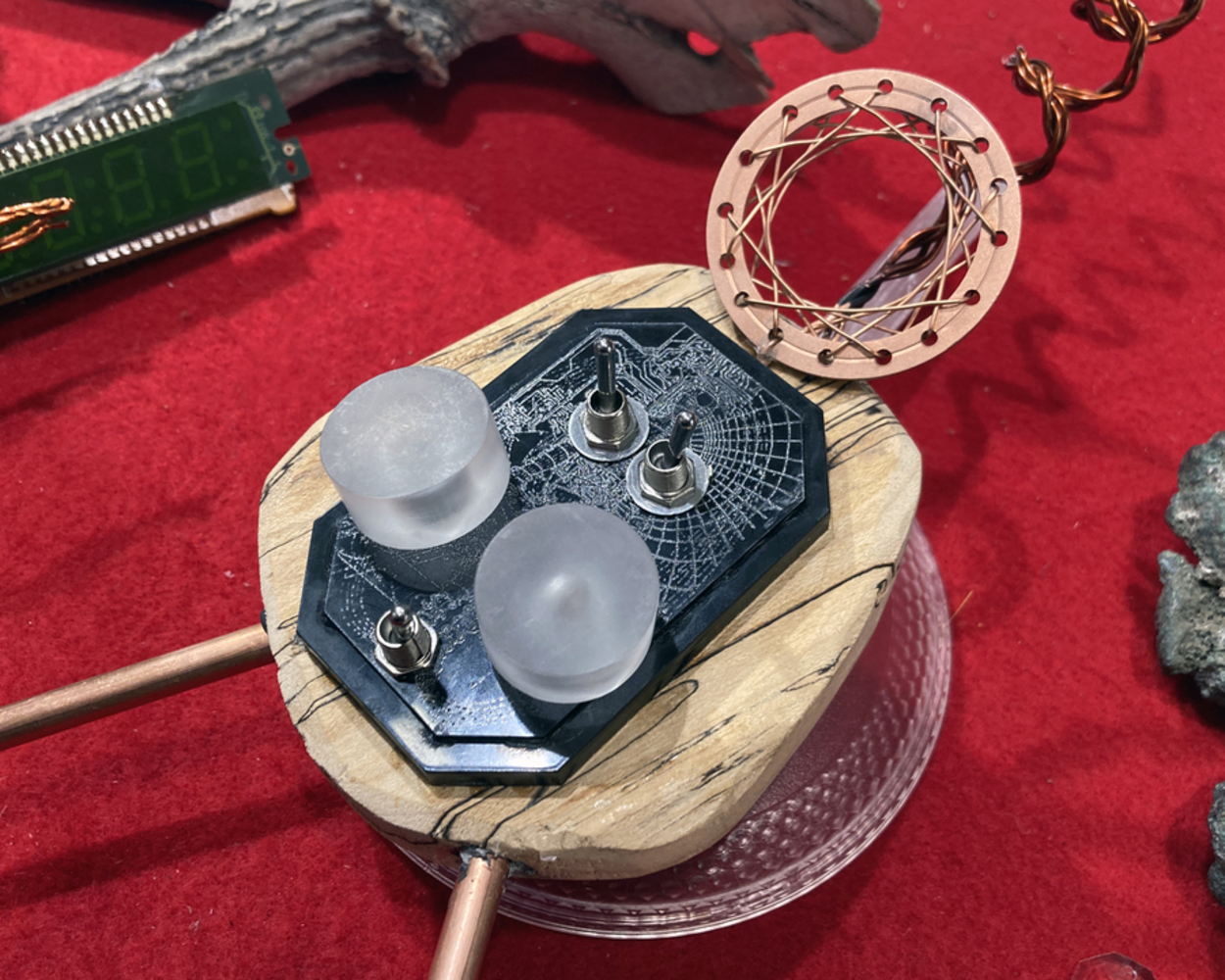
The interface is somewhat intentionally obtuse -making the use of this instrument rely on trial and error rather than explicit information made available to the user. The top left switch allow the user to swap between a mode for sensing wifi signals or a mode for sensing EMF signals. The top right swaps between using the long directional antenna or round non directional antenna.
The left knob controls the signal low threshold cut-off (any signal below this value is not registered on the motor) and the right knob controls the high threshold cut off which also affects the sensitivity as the signal is remapped between 0 and the high threshold value. Due to the noise of the various emf devices including the particle itself it's necessary to adjust these for each environment.
The lower most switch is connected to the enable pin on the particle argon - effectively an on/off switch for the device.
The process of using the device requires a lot of fiddling with the knobs in order to dial in a setting where the device is registering desired emf signals but not activating constantly. This makes the device's function somewhat mysterious and enigmatic - to be used only by an experienced practitioner. However, this process is not merely poetic as it is the same process necessary to isolate electronic signals for analysis which can prompt consideration to how we differentiate "signal" from "noise".
/*
 * Project OUIFI_DOWSING01
 * PHOEBE DEGROOT
 */
#include <neopixel.h>

#define NUMREADINGS 5

// PIN DEF -----------------------
uint8_t probepin1 = A0;
uint8_t probepin2 = A1;
uint8_t motor1 = D2;
uint8_t motor2 = D3;
uint8_t switch1 = D4;
uint8_t switch2 = D5;

uint8_t POTthresh = A2;
uint8_t POTband = A3;


// EMF Detection Vars -----------------------
uint8_t  LOWthresh = 5;
int HIGHthresh = 2000;

uint8_t  ct=0;
int total = 0;
int avg;
int readings[NUMREADINGS];

int wifi_reading;
int probe_reading;
bool useprobe1 = true;
uint8_t signal_mode = 1;
String modes[]={"DISABLED","EMF","WIFI LOCAL","WIFI GLOBAL"}; //different modes for singal data collection


typedef struct{
  unsigned long t=0;
  uint32_t delay;
  bool active = true;
}timer;

timer pubtimer = {0,1500,true}; //publishing timer

int probe_read(){
    int val; //
    uint8_t probepin;
    if (useprobe1){
        probepin = probepin1; //select antenna
    }
    else {probepin = probepin2;}

    val = analogRead(probepin);  // take a reading from the probe

    //revisit this code - average reading calculation
    if(val >= 1){
        val = constrain(val, 1, HIGHthresh);
        val = map(val, 1, HIGHthresh, 1, 255);
        total -= readings[ct];
        readings[ct] = val; //add value to reading
        total += readings[ct];
        ct++;          //adv index

    if (ct >= NUMREADINGS)
      ct = 0;         //

    avg = total / NUMREADINGS;
    return avg;
    }

    else { return 1; }
}


void publish_data(){
    if (signal_mode == 1){
        Particle.publish("probe-reading", String(probe_reading));
    }
    else if(signal_mode == 2){
        Particle.publish("wifi-reading", String(wifi_reading));
    }
}

void write_motor(){
    if (probe_reading>LOWthresh){
        int val = map(probe_reading,LOWthresh,255,50,255);
        analogWrite(motor1,val);
        analogWrite(motor2,val);
    }
    else{
        analogWrite(motor1,0);
        analogWrite(motor2,0);
    }
}

int wifi_read(){
    int strength;
    if (signal_mode != 3){
    WiFiSignal sig = WiFi.RSSI();
    float sigstr = sig.getStrength();
    // use the current connected wifi to read strength
    strength = int(sigstr);
    strength = map(strength, 0,100, 1, 255);
    }
    else{
        //search for strongest wifi signal from all available
    }
    return strength;
}

void check_switch(){
    if (digitalRead(switch1)==HIGH){
        useprobe1 = false;
    }
    else {useprobe1=true;}

    if (digitalRead(switch2)==HIGH){
        signal_mode = 2;
    }
    else {signal_mode = 1;}
}

void setup() {
    pinMode(switch1, INPUT_PULLUP);
    pinMode(switch2, INPUT_PULLUP);
    pinMode(motor1,OUTPUT);
    pinMode(motor2,OUTPUT);
    Particle.variable("probe",probe_reading);
    Particle.variable("wifi strength",wifi_reading);
    Particle.variable("low thresh",LOWthresh);
    Particle.variable("high thresh",HIGHthresh);

}

void loop() {

    LOWthresh = map(analogRead(POTthresh),4070,0,0,255);
    HIGHthresh = map(analogRead(POTband),4070,0,10,4000);

    probe_reading = probe_read();
    wifi_reading = wifi_read();

    check_switch();
    write_motor();

    if ((pubtimer.active) && (millis()-pubtimer.t>= pubtimer.delay)){
        publish_data();
        pubtimer.t = millis();
    }

    delay(5);
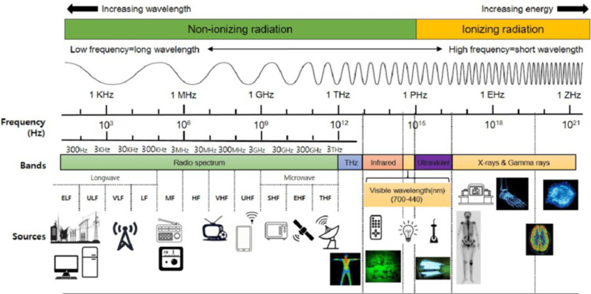
}Electromagnetic waves encompass a huge range of natural and technological phenomena from communications technology (radio, cellular phones, wifi etc) to xrays as well as the visible light spectrum. Most of these waves are imperceptible to humans and often not well understood making them a frequent subject of misinformation. Power transmission and electronics exhibit low frequency electromagnetic fields (EMF) on the order of 60Hz whereas radiofrequency EMF (RF EMF) for communications operate between about 100KHz (long-wave radio) to 300GHz (satellite and radar transmissions). Other RF EMF frequencies of note are FM radio (87-108 MHz), Cell towers (700-1900 MHz), Bluetooth (2402-2480 MHz), WiFi (2.4-5 GHz) and cell phones (0.7-2.7GHz for 2nd-4th gen and up to 80GHz for 5th gen or "5g"). Exposure to certain EMF is undeniably dangerous such as Xrays and gamma rays but there is ongoing study about the effects of RF EMF on health and well-being- but it is clear there is no clear cut boundary between "safe" or "unsafe" EMF as the power density, amplitude, saturation and frequency are all important factors. I also suspect that due to the abundance of unfounded pseudo-scientific beliefs concerning EMF, real potential hazards of RF EMF in our environment may be ignored by tech companies and the general public.
In EMF mode the OUIFi reacts most strongly to EMF from power-sources (outlets, lighting, high power electronics) as well as certain wireless devices such as RFID readers. This is likely due to the higher amplitude (higher power) and lower frequencies of these waves being easier to pick up by the relatively crude antenna and the signal is strong enough to be differentiated from the background noise compared to the lower power communication signals. It was particularly sensitive to older fluorescent light bulbs, analog electronics and dust collection - the latter possibly due to the creation of static. In WiFi mode the signal was a little hard to differentiate possibly due to the high signal coverage in the areas I was testing in.
It's my hope that this project prompts further inquiry about EMF both to dispel harmful rumors and to bring critical inspection on the unseen effects of building connected futures.
More resources on RF EMF:
Radio Frequency Electromagnetic Fields Exposure Assessment in Indoor Environments: A Review
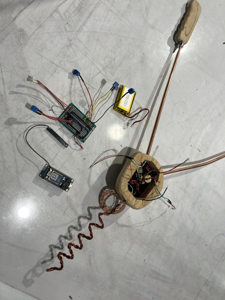
The primary obstacle in developing this project was building a successful antenna system - an EMF antenna is deceptively simple - just an piece of conductive material attached to an analog input. However getting the antenna to work effectively is much harder. I ended up trying about 6 different antenna designs - the large coil was the most sensitive but was somewhat directional and an alternative version of the copper disc was a good non-directional antenna - the woven disc antenna that is on the final device was less effective than a more solid disc but the larger coil antenna was strong enough that the additional antenna was more aesthetic than functional anyway.
The analog input of the antenna needed to be pulled to ground over a very high impedance resistor on the order of (4+ MOhm) in order to function - which is a somewhat uncommon resistor value. I was able to find a 10 MOhm resistor in stock at ideate. The vibration in the handles is created using two small "pager" vibrating dc motors connected to the Li+ power rail modulated by PWM from the Particle Argon via two pn2222A transistors. The rest of the circuit is relatively straightforward with two potentiometers connected to analog inputs and three digital inputs for the three switches.
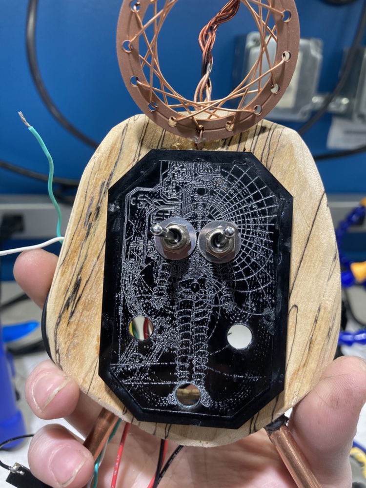
I wanted to make the final product feel polished and not readily discernible as simple microcontroller-based device; instead looking like something more akin to the esoteric inventions of Nikolai Tesla or Thomas Edison. I built a protoboard to connect the three switches, two potentiometers, two antennas and two actuators with the Particle Argon board and battery in a fairly compact envelope. The enclosure was cut out of a piece of spalted maple with a black acrylic face plate and turned clear acrylic knobs for the potentiometers. The handles are two pieces of spalted maple connected to the enclosure with two copper tubes through which the motor wires are routed. The motors themselves get embedded in a hole inside of the handles.
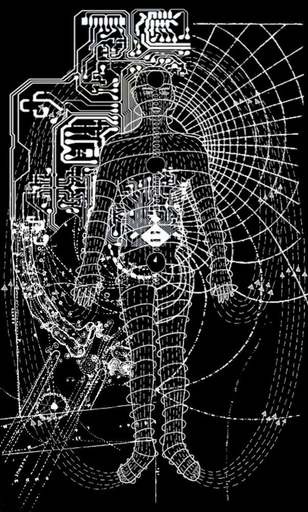
The front face plate was laser etched with an image composed from a couple of different found diagrams - a pcb trace for a wireless device, the curvature of a magnetic field, a map of dowsing lines around the Stonehenge site and a figure from an article on "polarity therapy" first drawn by author Randolph Stone. Originally I also planned on placing either lights or an additional knob for a tuning capacitor on the plate but ended up with the five shown below. To make the interface a little less confusing I tried to make the control placement somewhat related to the etched image- the on/off is at the feet , low and high cut offs are on the left and right side of the figure, the emf/wifi mode is on the left ( near the pcb diagram) and the antenna selection is on the right.
In the future I would like to refine this project to improve the detection capabilities primarily through improvement of the electronic circuit. Specifically I'd like to try additional antenna designs - possibly incorporating an external connector so antennas can be swapped out - and add in a variable capacitor or other method to narrow the target frequency for detection. I suspect an issue with my current design is that the low power EMF from communication transmissions are hard to detect against a noisy background of higher power EMF from AC powered electronics.
Additional work in wire routing, noise isolation and getting some sort of measurable metric from the antenna signal would help improve the precision of the device. While I don't think this is necessary for OUIfi to be effective, additional precision may be necessary for the process of developing frequency tuning.
Finally I want to look further into possible applications of the connected ecosystem the particle argon platform enables. Diverging from the more speculative focus I could see applications in EMF level monitoring to say encourage a user to decrease the amount of electronics use in their environment or to notify in the case of unusually high EMF exposure if say a large power transformer were installed. Another idea I had was for the device to collect the EMF signal data over a time interval along with relevant contextual data such as geolocation and collection time/date which could be visualized as a graph or sound clip. If the device is able to scan over different frequencies this could create a sort of "snapshot" of these invisible signals - helping the use better understand the energetic waves in their environment.
References:
DIY Ultra Sensitive EMF Detector, Mirko Pavleski- this project was the primary inspiration for the code and electronics for EMF detection
https://create.arduino.cc/projecthub/mircemk/diy-ultra-sensitive-emf-detector-4be895