Project Proposal: Soft Pressure Mat
Made by Joseph Paetz
Made by Joseph Paetz
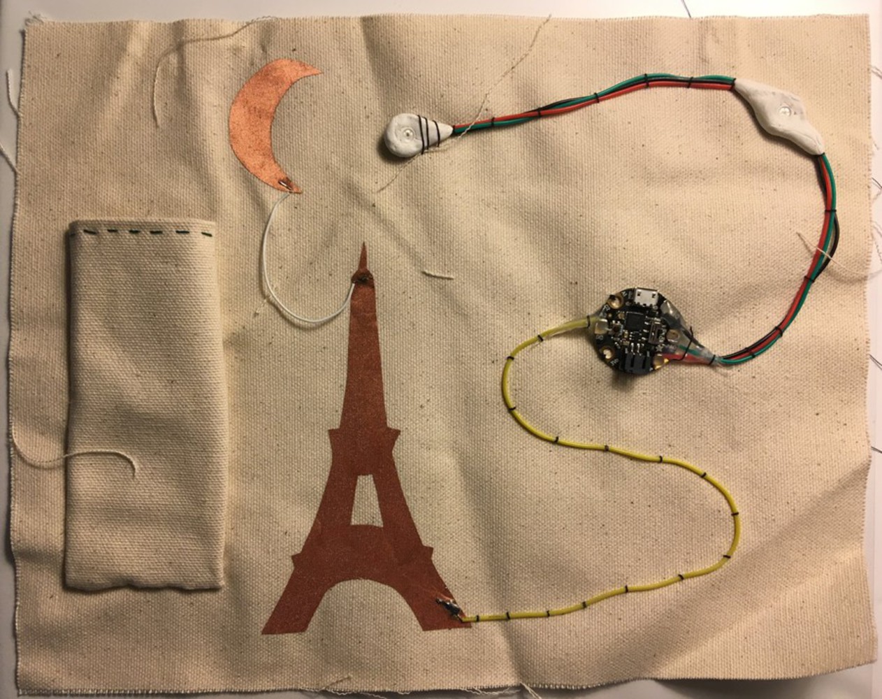
This is the final project for the E-textiles micro course. It includes pictures of my sample book and a proposal for a soft pressure mat.
Created: March 9th, 2018
My proposed project is a fabric pressure map for a smart scoliosis brace that is being designed for the Rapid Prototyping of Computer Systems class. The pressure map will be attached to the shirt the patient wears underneath the brace, and will allow them to identify the locations on their body that the brace is applying pressure. These locations can then be compared to the locations that the clinician has specified, and the effectiveness of the brace position can be evaluated (see: "A 3D visualization tool for the design and customization of spinal braces"). If the brace is in an incorrect position, the patient can be prompted to adjust the brace into the correct position. Ideally, the pressure map would also be able to provide information about the value of the pressure being applied, but other sensors may have to be employed to determine this.
The functional requirements of this pressure map are:
I started my research by checking the sensor section of Kobakant's "How to Get What You Want". There were a few pressure matrix designs, but the machine sewn version caught my eye because it is machine sewn and thus faster to fabricate. The pressure matrix uses a piezo resistive conductive fabric with conductive fabric sewn horizontally on one side and vertically on the other. The resistance between any horizontal/vertical pair of conductive threads can be read to determine how much pressure is being applied at the crossing point of the two threads (because the conductivity of the fabric decreases when under pressure). From the pictures provided by Kobakant, I noticed a few things that I will need to take into account when designing the pressure matrix. First of all, there is a picture of fingertips with a black residue from the conductive fabric. This means I will likely need to layer regular fabric on either side of the pressure mat to avoid this residue getting onto the brace or the patient (this will also help to insulate the threads from moisture that might build up under the brace). The second thing I noticed was that when pressure is applied to one thread crossing, pressure is sensed at several points (but localized at the point where the pressure is actually applied). This means there may need to be some data processing to determine where the pressure is actually applied (although I don't know what this processing will actually be).
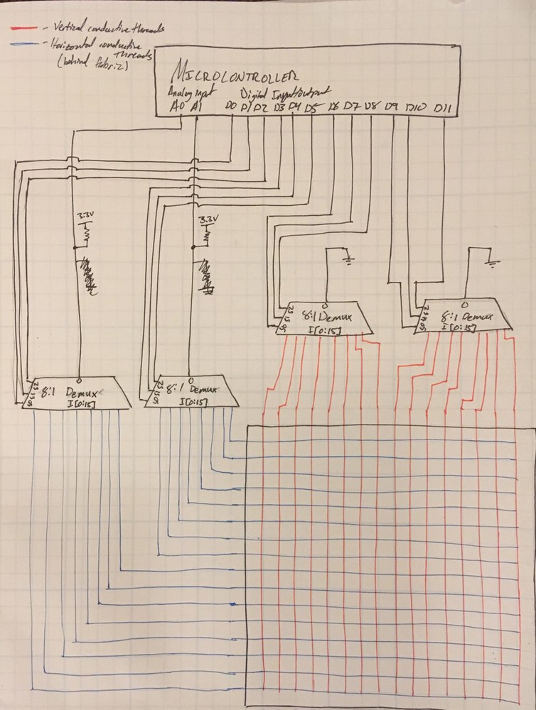
I thought that the Kobakant sample would be a good jumping off point, so I looked into the details of the implementation. I was able to find machine sewable conductive thread on Adafruit quite easily. Finding piezo-resistive conductive fabric was a bit difficult as all the suppliers seemed to be out of stock. Luckily, I found some on Mouser. The next issue was how to read all of the conductive threads. This depended on how big the pressure matrix was going to be. If the pressure map didn't have many points, I could read it using analog inputs on a microcontroller. If there were many, many points, I would have to use a multiplexer to allow me to read many of the threads with few analog pins. I will assume that we will need a multiplexer, because even a 10x10 pressure matrix requires 10 analog inputs (For a nxm pressure matrix, (n) analog inputs need to be read for a total of (n*m) points).
While we do not know the exact dimensions of the pressure map, I will start with two square foot mats that can be positioned where the brace's pressure is intended to be applied. I have also shown that conductive thread is used to carry signals until the top of the brace is reached. This is done to prevent the use of wires under the brace where they will almost certainly cause irritation. I have also included the circuit I will begin my testing with. I have included multiplexers as I expect the pressure map to be large enough that the microcontroller will run out of analog pins.
After researching and designing the pressure matrix, I am more confident that it is feasible, and I am now aware of some sticking points that I will need to watch out for (residue from the piezo-resistive fabric and pressure readings that are not isolated to the point where pressure is applied).
However, I also have several new questions that I will need to answer as I start prototyping with the material:
In this class, students learn to create active, responsive and flexible artifacts using microcontrollers, electroluminescence wire, muscle wire, and electronics embedded fabric. This course also pr...more
This is the final project for the E-textiles micro course. It includes pictures of my sample book and a proposal for a soft pressure mat.