Skill Dev II: Working with Inputs and Sensors
Made by Kevin Chou
Made by Kevin Chou
The goal of this project was to become acquainted with some of the sensors in the kit, incorporate them into circuits/code to produce actions and feedback, as well as to become familiar with conditional logic.
Created: November 3rd, 2022
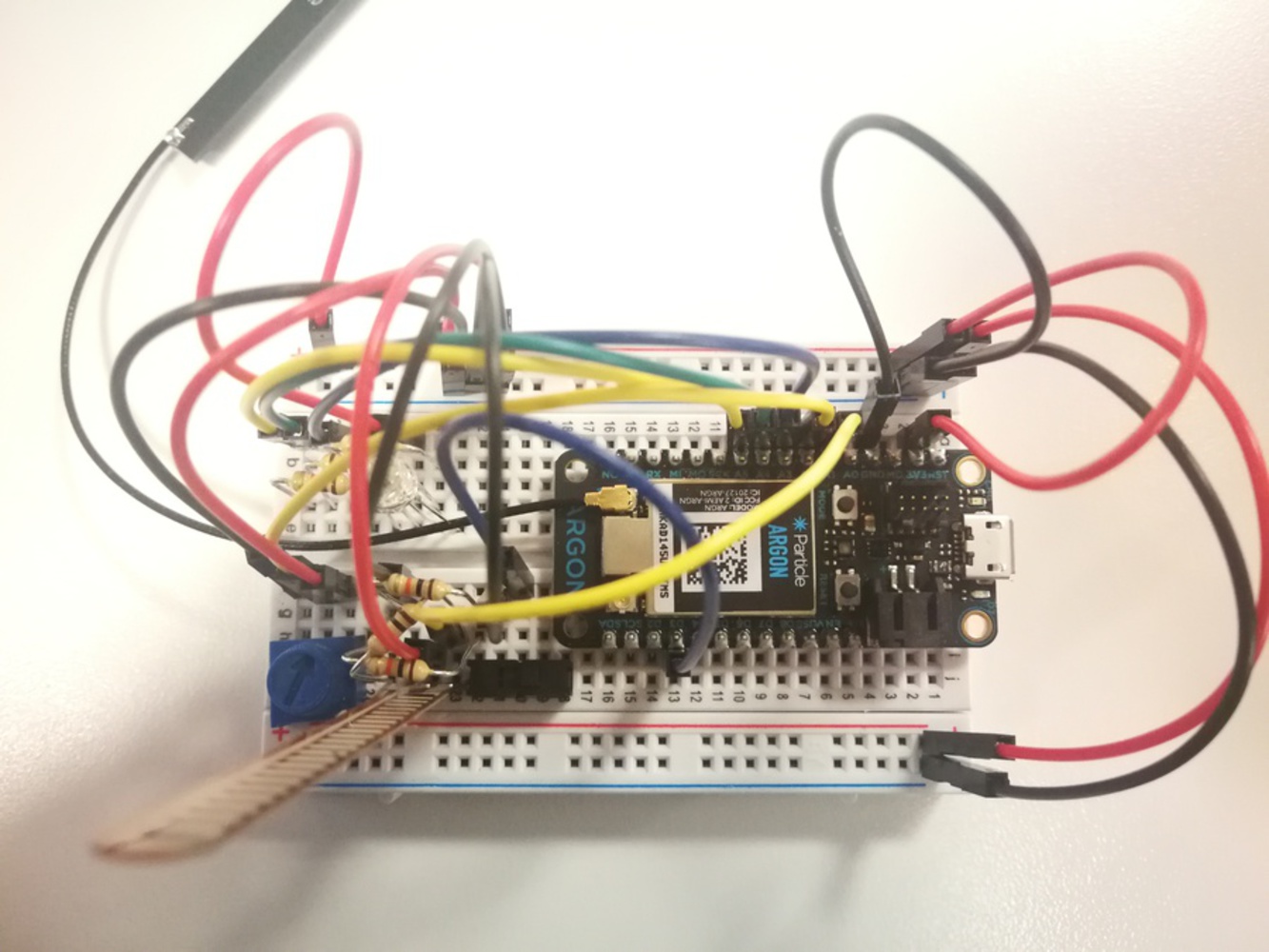
In this project, a switch, flex sensor, and potentiometer were used to control an RGB LED in different ways:
int redPin = A5;
int greenPin = A4;
int bluePin = A3;
int redValue = 255; // Full brightness for an Cathode RGB LED is 0, and off 255
int greenValue = 255; // Full brightness for an Cathode RGB LED is 0, and off 255
int blueValue = 255; // Full brightness for an Cathode RGB LED is 0, and off 255
//--------------------------------------------------------------------------------
int potPin = A2;
int potReading = 0;
//--------------------------------------------------------------------------------
// Our button wired to D3
// We wire D0 to the middle terminal on the switch
// And any of the two other terminals to ground
int switchPin = D3;
int switchState = LOW;
//--------------------------------------------------------------------------------
int flexPin = A1;
int flexReading = 0;
//--------------------------------------------------------------------------------
int RGBControl(String command){
//0 is HI, 255 is LOW b/c CATHODE RGB LED
String colors[3];
colors[0]="";
colors[1]="";
colors[2]="";
int index = 0;
for( int i = 0; i < command.length(); i++ )
{
if( index < 3 ){
char c = command.charAt(i);
colors[index] += c;
if( c == ',') index++;
}
}
// get the red component...
redValue = colors[0].toInt();
// now green
greenValue = colors[1].toInt();
// now blue
blueValue = colors[2].toInt();
// write the mixed color
analogWrite( redPin, redValue);
analogWrite( greenPin, greenValue);
analogWrite( bluePin, blueValue);
return 1;
}
void setup() {
//Uses CATHODE RGB LED, 255 is OFF, 0 is ON
pinMode(redPin, OUTPUT);
pinMode(greenPin, OUTPUT);
pinMode(bluePin, OUTPUT);
//Start up as OFF
analogWrite(redPin, 255);
analogWrite(greenPin, 255);
analogWrite(bluePin, 255);
//RGB w Particle
Particle.function("RGB LED", RGBControl);
//Pot w Particle
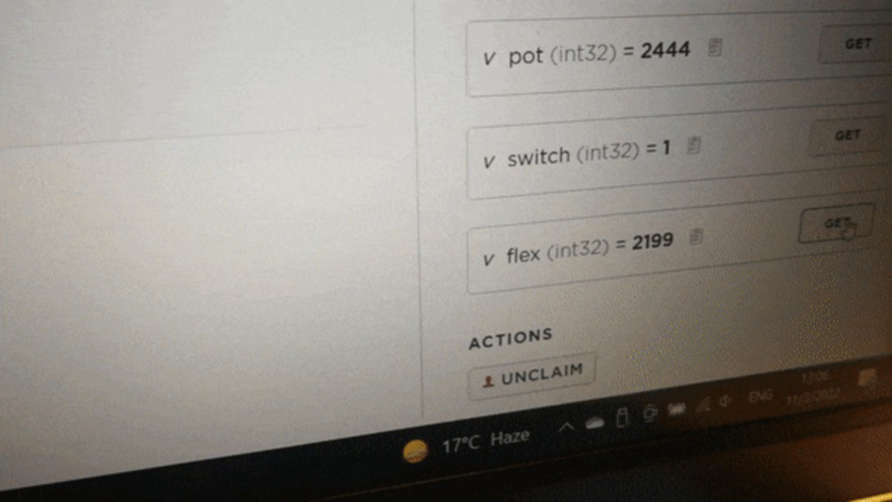
Particle.variable("pot", potReading);
//Switch pulled high
pinMode(switchPin , INPUT_PULLUP); // sets pin as input
Particle.variable("switch", switchState);
Particle.variable("flex", flexReading);
}
void loop() {
switchState = digitalRead( switchPin );
if( switchState == LOW ){
// turn off all LEDs
analogWrite(redPin, 255); //255 is OFF
analogWrite(greenPin, 255); //255 is OFF
analogWrite(bluePin, 255); //255 is OFF
}
else{
// Use analogRead to read the potentiometer reading
// This gives us a value from 0 to 4095
potReading = analogRead(potPin);
flexReading = analogRead(flexPin);
blueValue = map(flexReading, 1270, 1890,0,255);
// Map this value into the PWM range (0-255)
// and store as the led brightness
//redValue = map(potReading, 0, 4095, 0, 255);
redValue = map(potReading, 18, 4037, 0, 255); //actual pot range is about 18-4037
analogWrite(redPin, redValue);
analogWrite(bluePin, blueValue);
}
delay(100);
}Reusing my code and wiring for the RGB LED from Skill Dev I, I decided to use the potentiometer and flex sensor as they both had variable resistance that could be mapped to PWM to control the intensity of the LED. Since neither sensor was ideal, I had to modify their expected analog ranges when mapping them to PWM to match their actual limits so that the LED would actually be able to turn fully OFF and ON. I also added a switch as I initially misread the prompt as requiring 3 sensors, and wanted to turn off the LED when I was modifying code without unplugging the board since the Argon is a little finicky about uploading code. In particular, every time I had to flash new code after plugging the board in, it would be stuck trying to connect to the cloud until I reset it after plugging it in for some reason.