Skills Dev2 : Rahul Jha
Made by Rahul Jha
Made by Rahul Jha
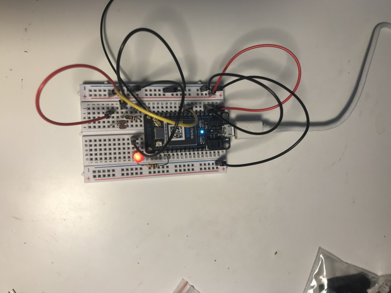
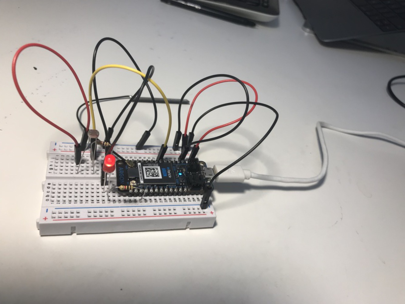
simple 2-in (sensors or inputs) 1-out (LED) device - representing automatic lights on/off system based on the natural light intensity in a room
Created: November 24th, 2021
1. Initially connected an LED to the argon board and connected it at D2 pin.
2. Next wired photo sensor on the board using a pull-down resistor of 10 K ohm and connected it to A4 pin.
3. Developed the sketch (program ) to simply control the LED intensity with the corresponding change in the intensity of light falling on the photosensor.
4. Shared the value of photosensor online using 'particle.variable'.
int ledPin = D2;

int photoresPin = A4;
int photoresRead = 0;

void setup() {

    //Set the LED as Output
    pinMode(ledPin, OUTPUT);


    Particle.variable("photoResValue", photoresRead);

}

void loop() {

    //0-4095
    photoresRead = analogRead(photoresPin);

    //using map function to convert the range
    int brightness = map(photoresRead, 0 , 4095, 0, 255 );

    analogWrite( ledPin, brightness );

    delay(200);

}Link for youtube video (photo-resistor as sensor input and LED as output):
int ledPin = D2;
int switchPin = D4;
int switchState; //store the reading from the button
int switchState_prev = LOW;

int photoresPin = A4;
int photoresRead = 0;

void setup() {

    //Set the LED as Output
    pinMode(ledPin, OUTPUT);

    //Set the switch as input
    pinMode (switchPin, INPUT_PULLUP);

    Particle.variable("photoResValue", photoresRead);

}

void loop() {

    switchState = digitalRead( switchPin );


    if(switchState == HIGH){


        // added the below code to make sure publish happens only when..
        // switch state changes from previous state
        if (switchState != switchState_prev){
            Particle.publish( "Switch ON" );
        }
        switchState_prev = switchState;

        //0-4095
         photoresRead = analogRead(photoresPin);

        //using map function to convert the range
        int brightness = map(photoresRead, 0 , 4095, 0, 255 );

        analogWrite( ledPin, brightness );

        delay(200);

    }else{

        if (switchState != switchState_prev){
             Particle.publish( "Switch OFF" );
        }
        switchState_prev = switchState;


        int brightness = 0;
        analogWrite( ledPin, brightness );

    }
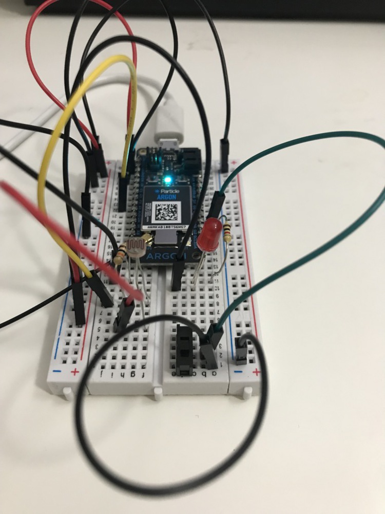
}Link for youtube video (after adding third component: second input - toggle switch):
https://youtu.be/Ky0jvFmMy0k