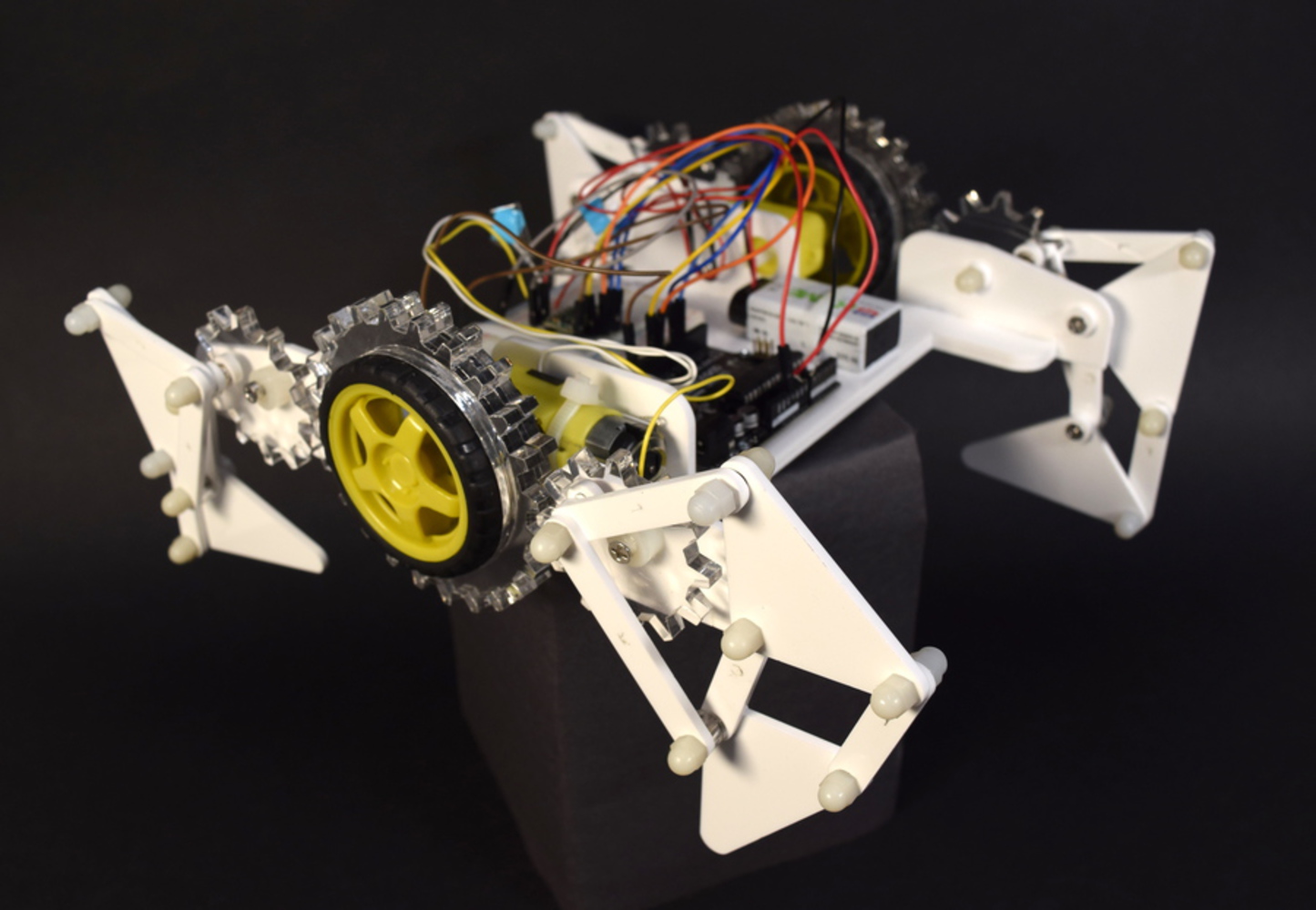
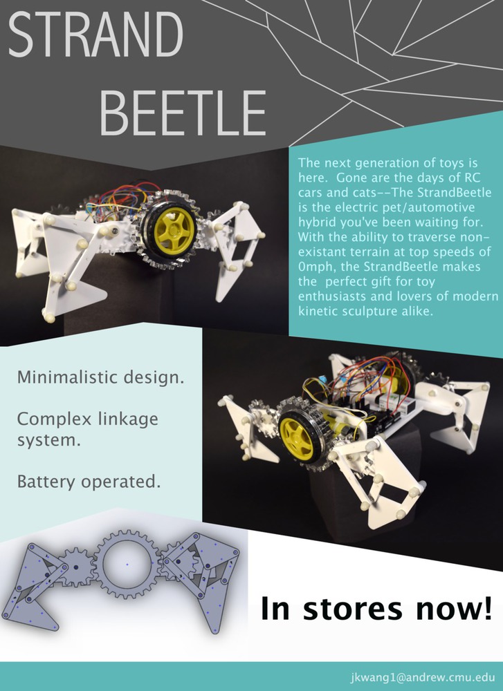
StrandBeetle
Made by Jen Kwang
Made by Jen Kwang
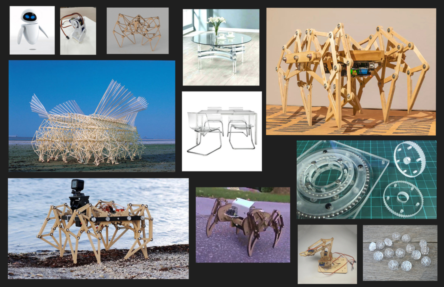
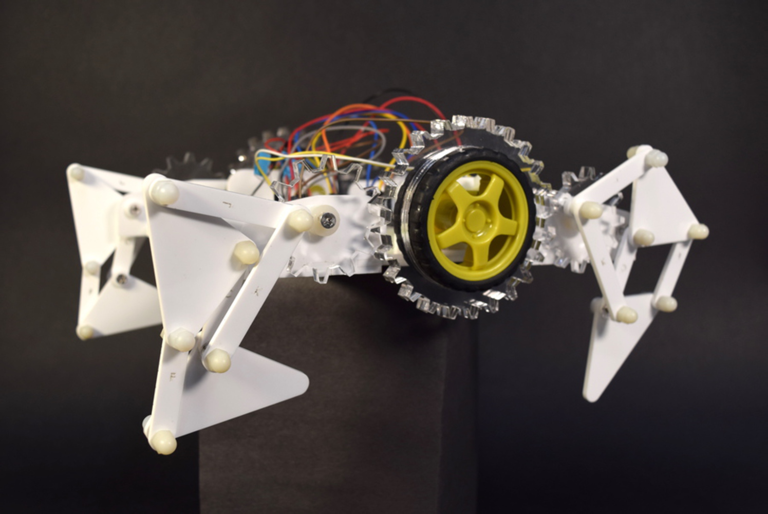
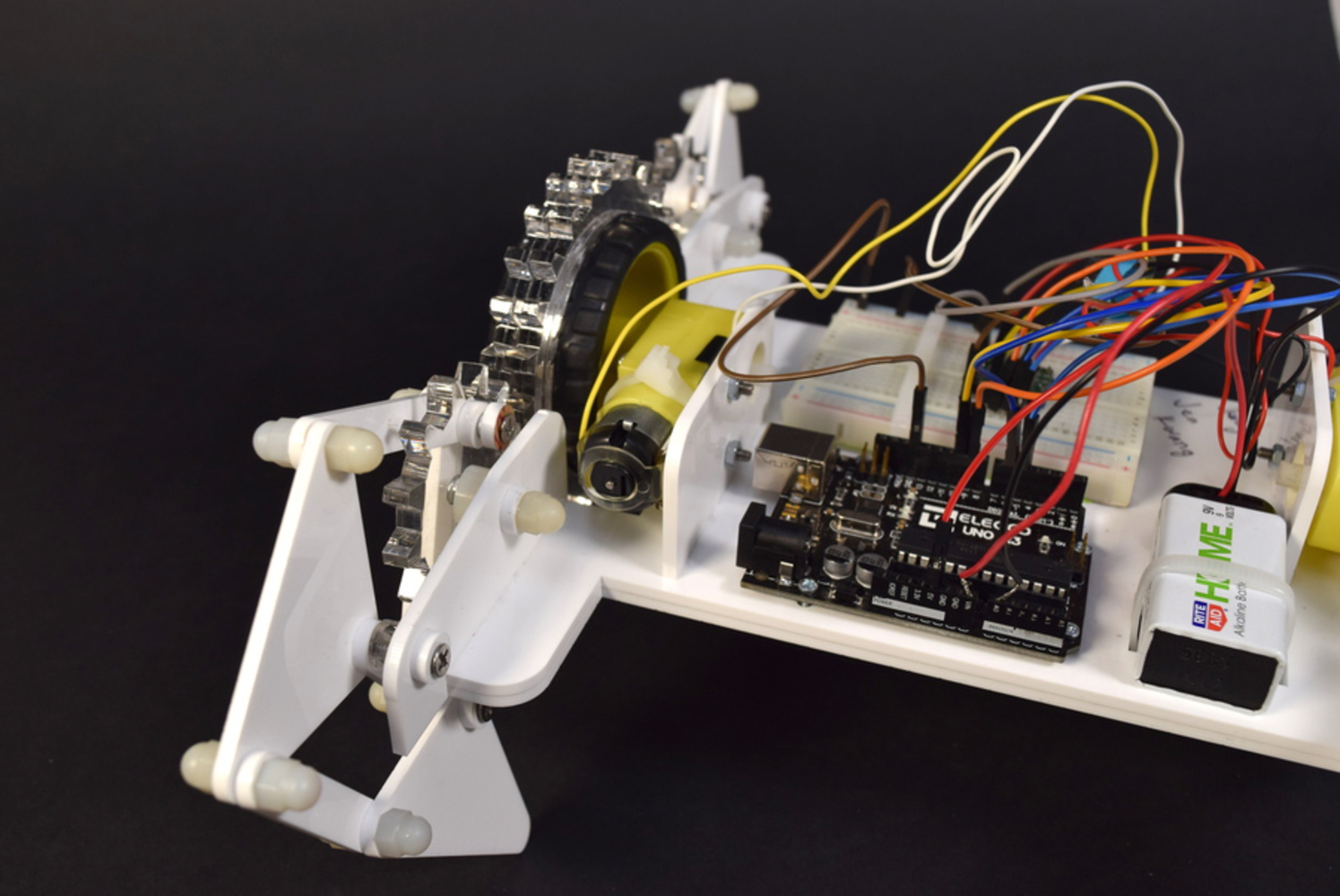
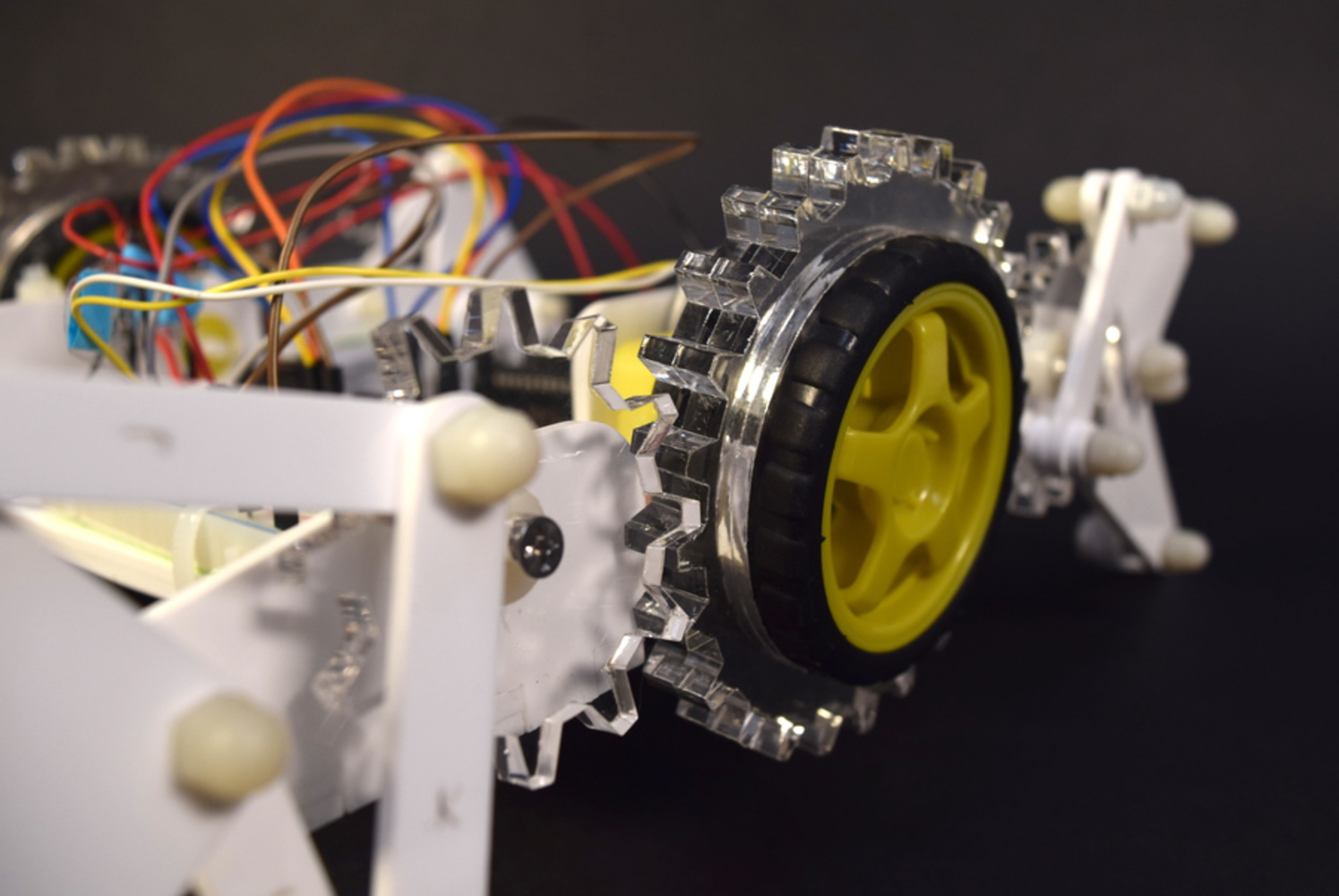
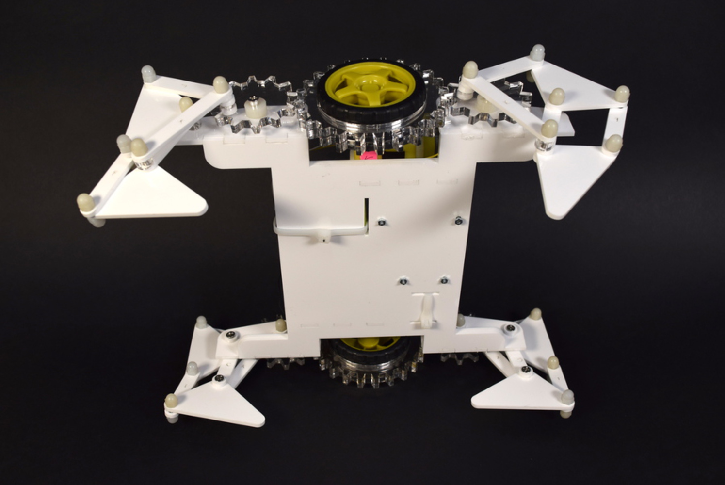
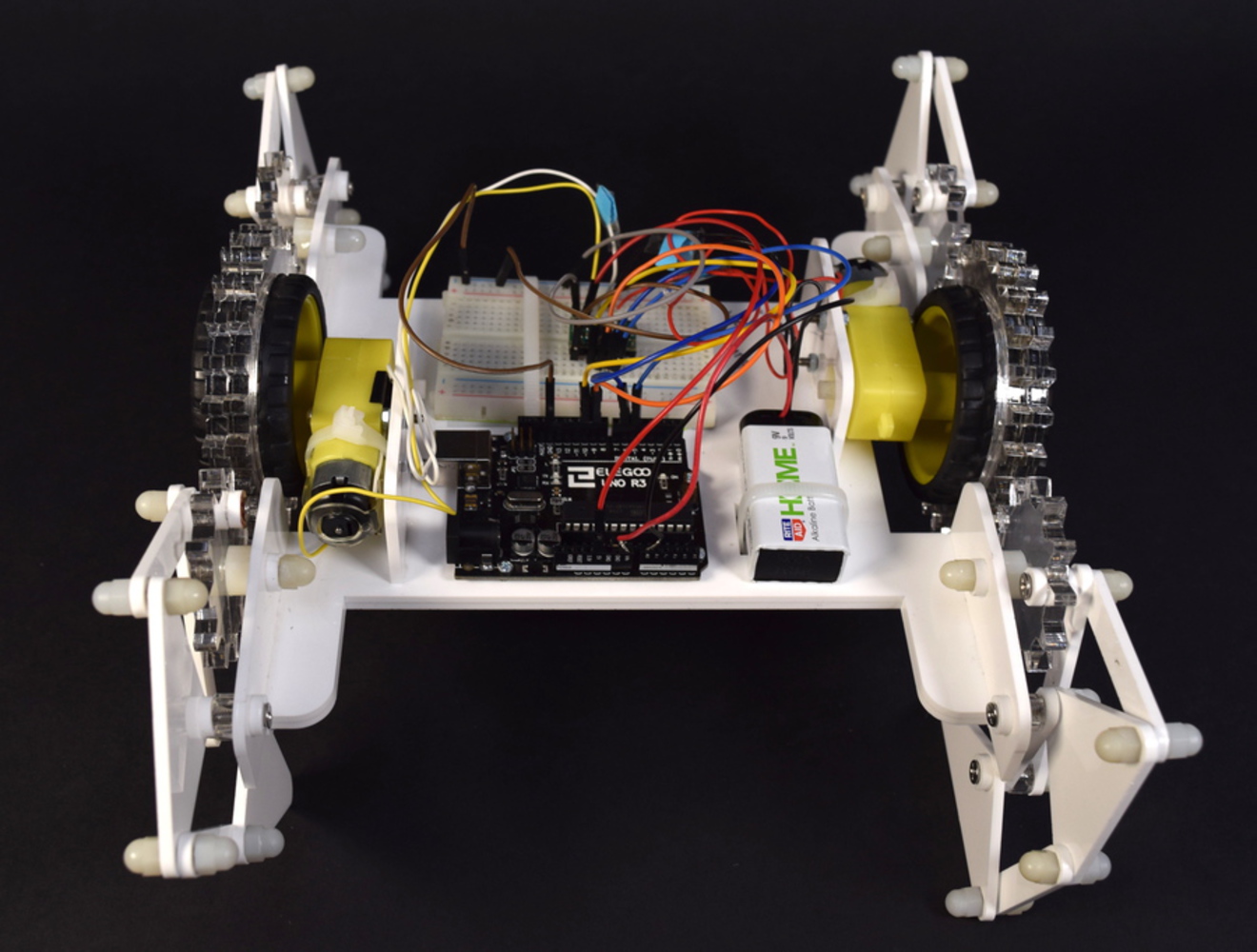
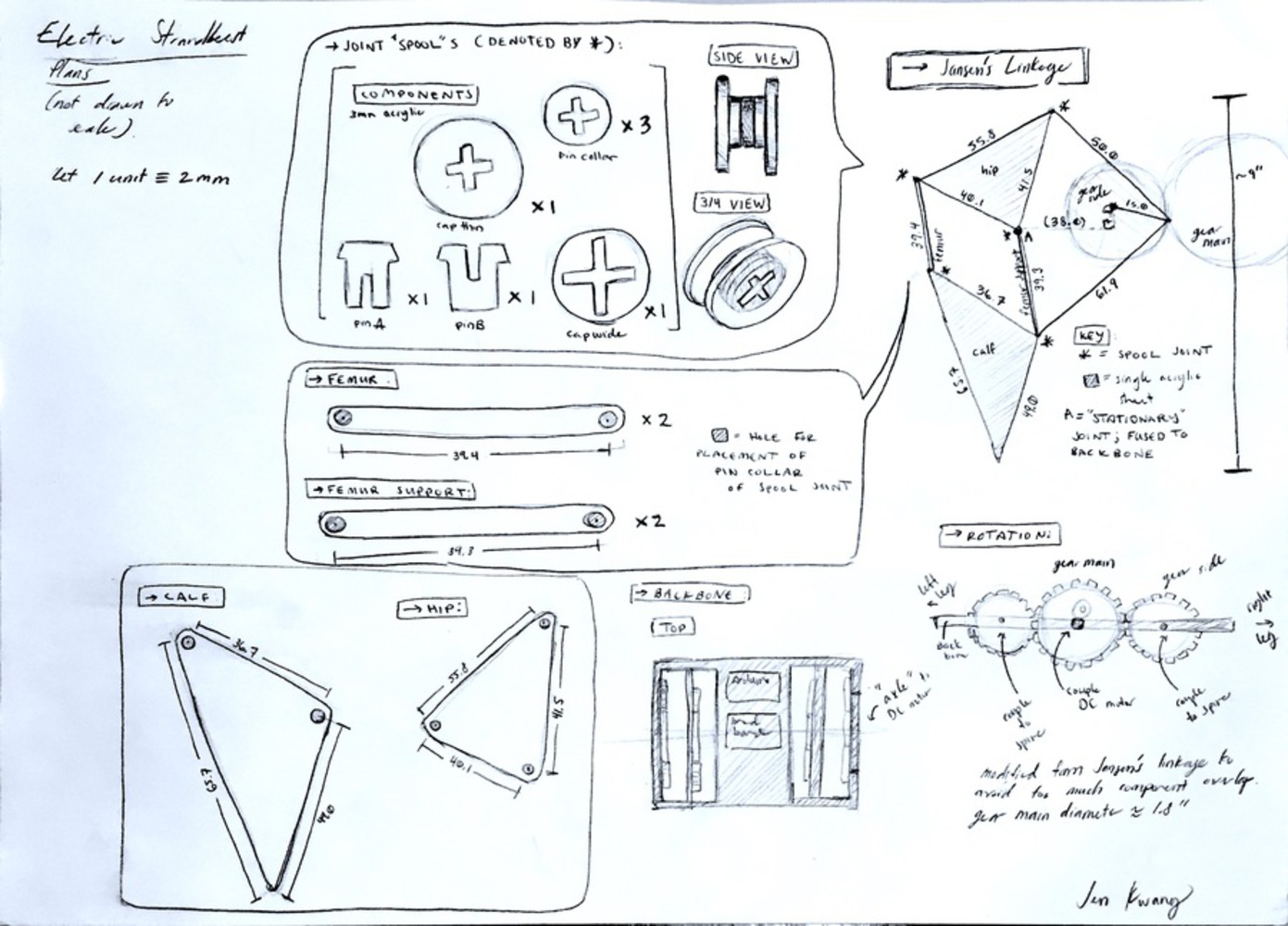
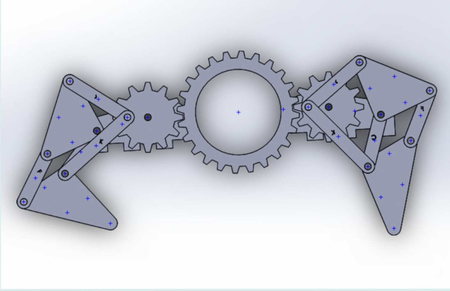
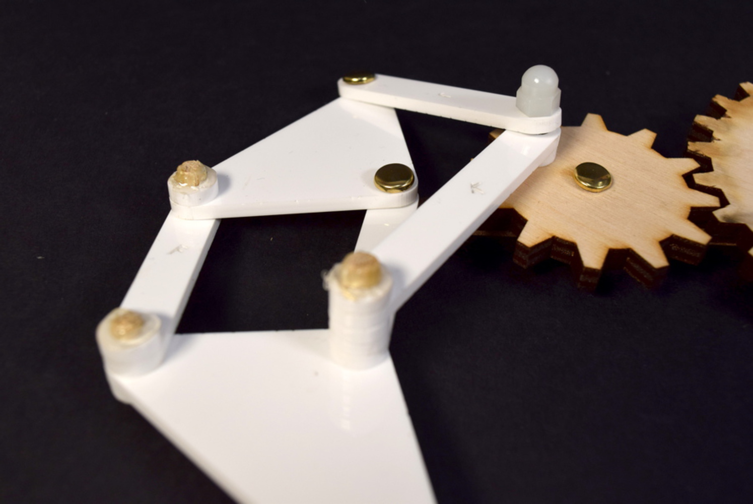
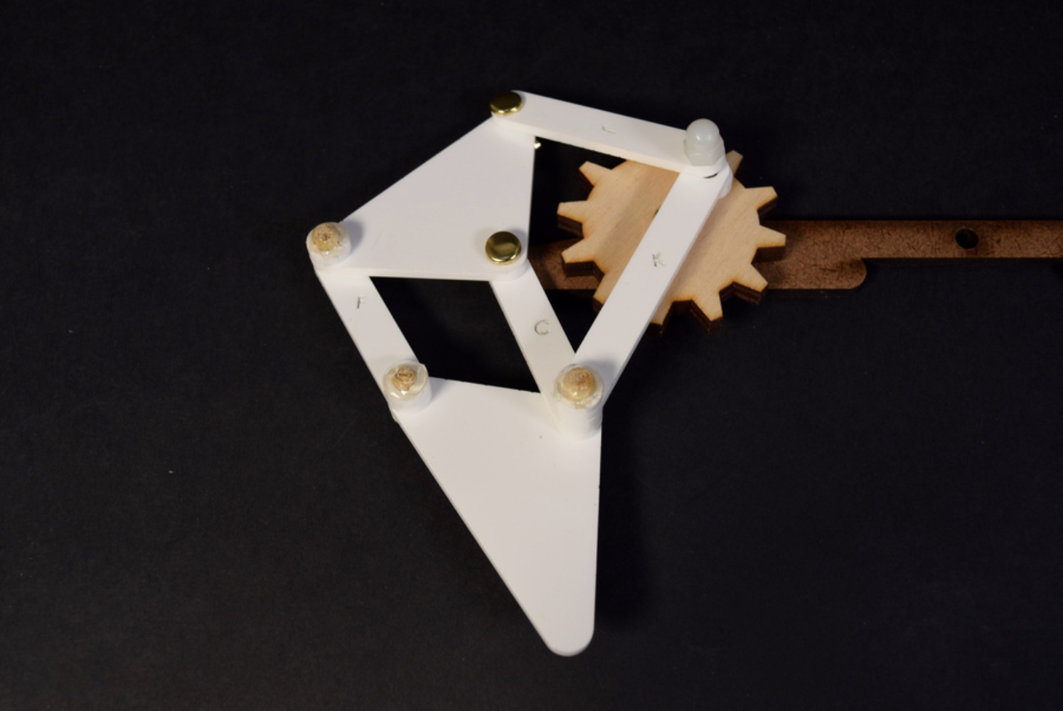
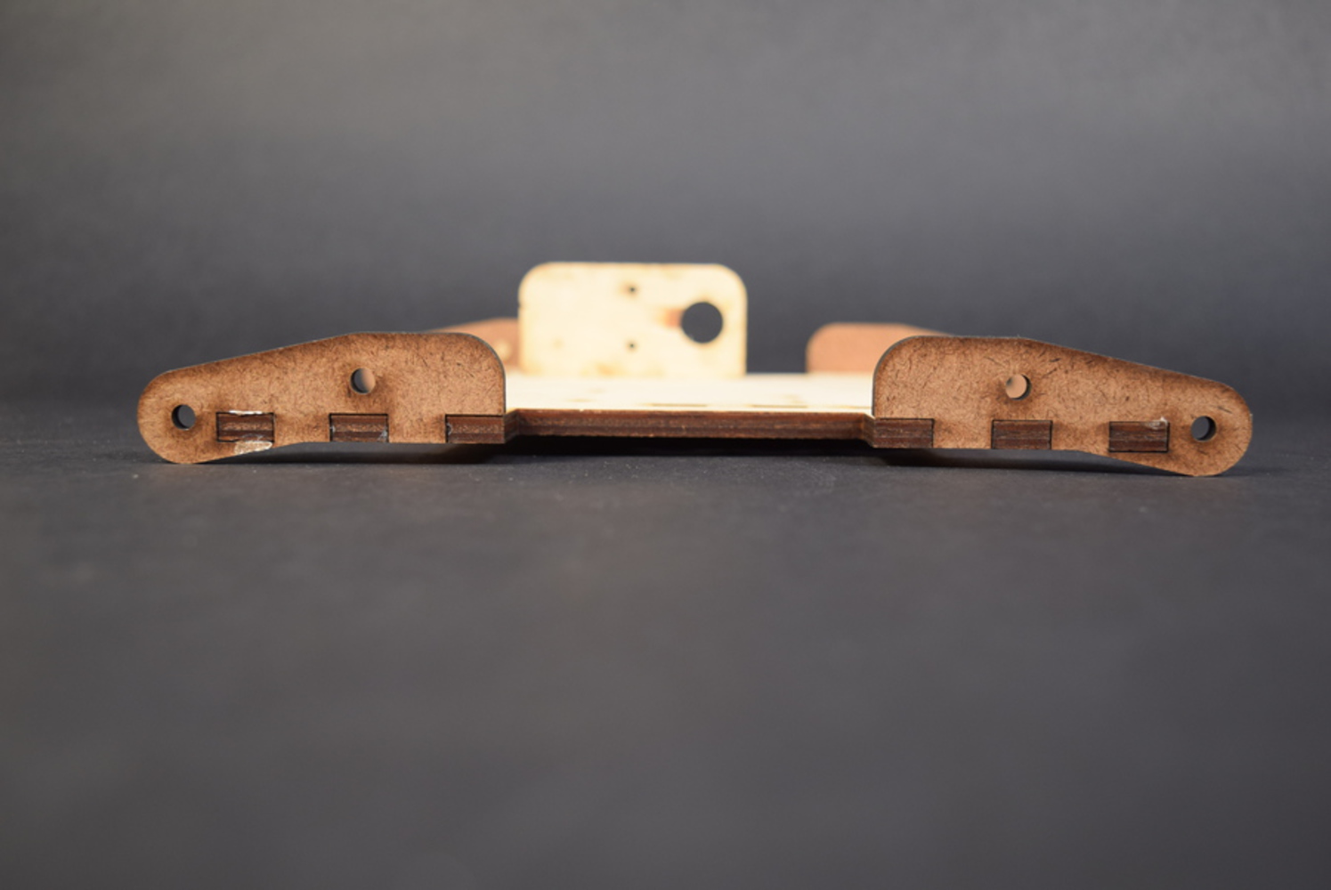
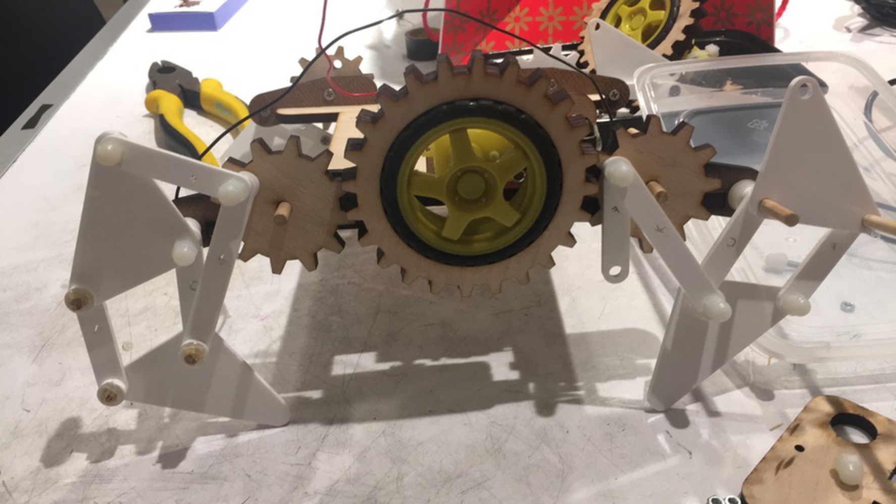
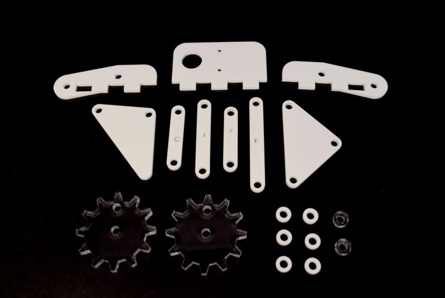
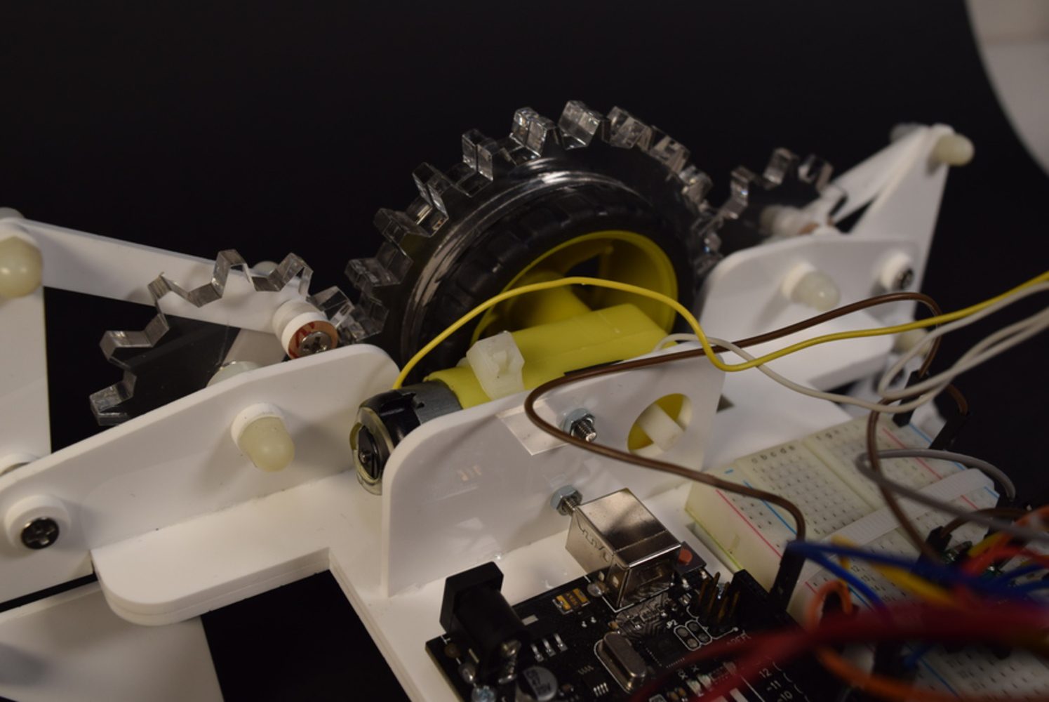
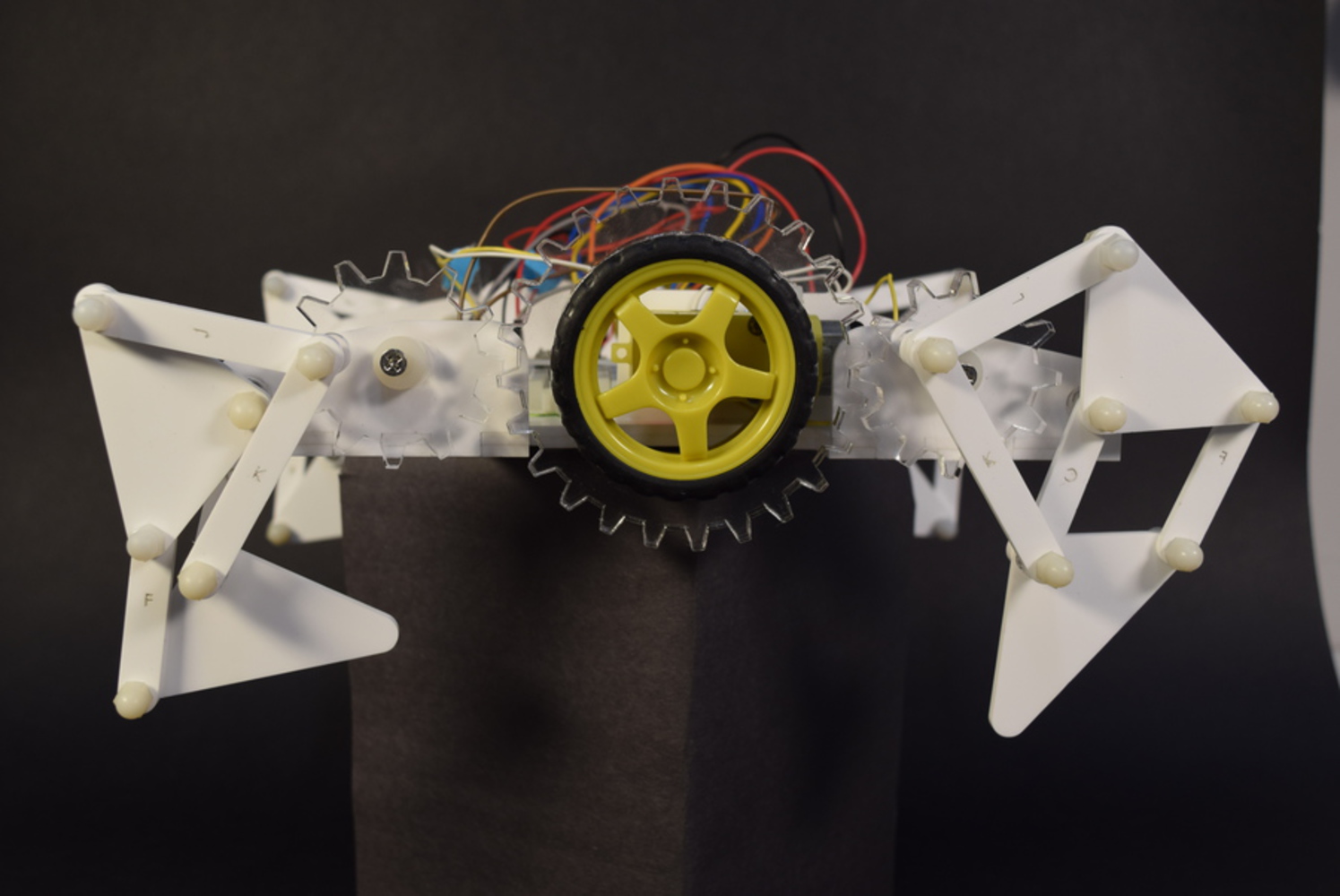
A small electric walking robot based on usage of Jansen's linkage.
Created: May 2nd, 2019

Offers students hands-on experience in DIY product design and fabrication processes. Students work individually or in small groups to design customized and personalized products of their own and bu...more
A small electric walking robot based on usage of Jansen's linkage.