Skills Dev I: Jody - Blinking LED & Dimmer
Made by jmadala
Made by jmadala
First time with Particle platform to build LED circuit with dimmer function and connected color LED.
Created: November 2nd, 2020
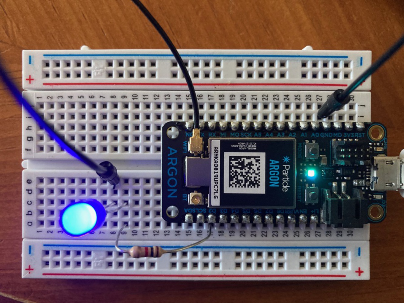
Created a blinking LED, connected dimmer & connected color LED (RGB).
//Declare variable ledPin as an integer
//Set ledPinI to D2 on argon
int ledPin = D2;
//setup is called once every time a program is run
void setup() {
//tell argon to use D2 as the output pin
pinMode(ledPin, OUTPUT);
}
void loop() {
//turns pin on
digitalWrite(ledPin, HIGH);
//for 1000 milliseconds
delay(1000);
//turns pin off
digitalWrite(ledPin, LOW);
//for 1000 milliseconds
delay(1000);
//repeats loop
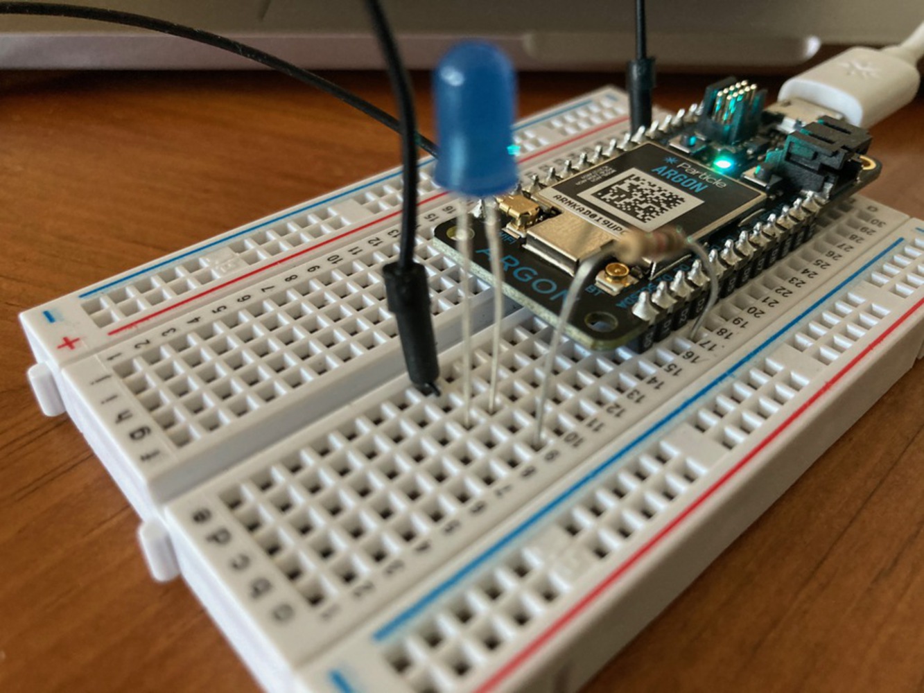
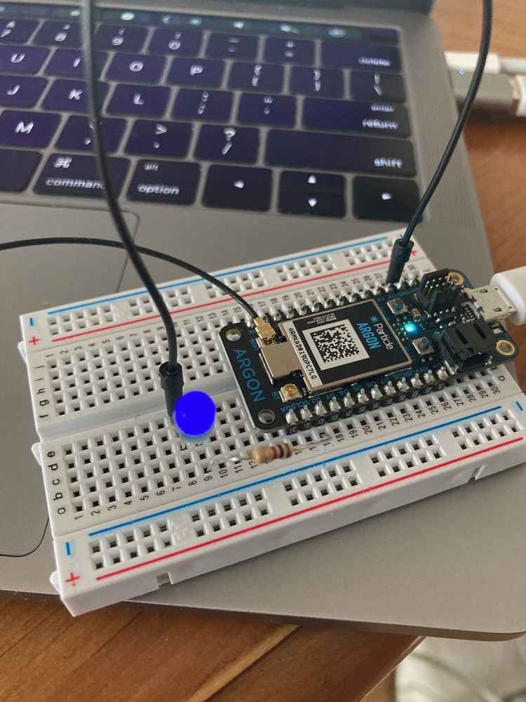
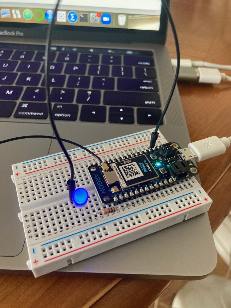
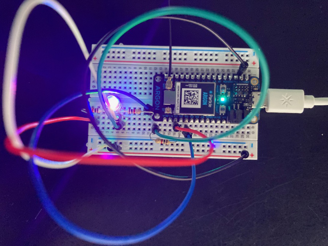
}I followed the process shared in class as well as in the tutorial. I found re-watching the class recording helpful, since I had some trouble initially understanding where items were getting pinned (which slots in the breadboard). I also found that I had to wiggle my LED a bit to get it to light up the first time. I also completed the 1st part of the optional exercise - setting the dimmer/brightness of the LED via the Internet and included a couple of pictures below. The tutorial for using the RBG LED was confusing for me and I didn't understand what the steps were explaining, so I skipped it.
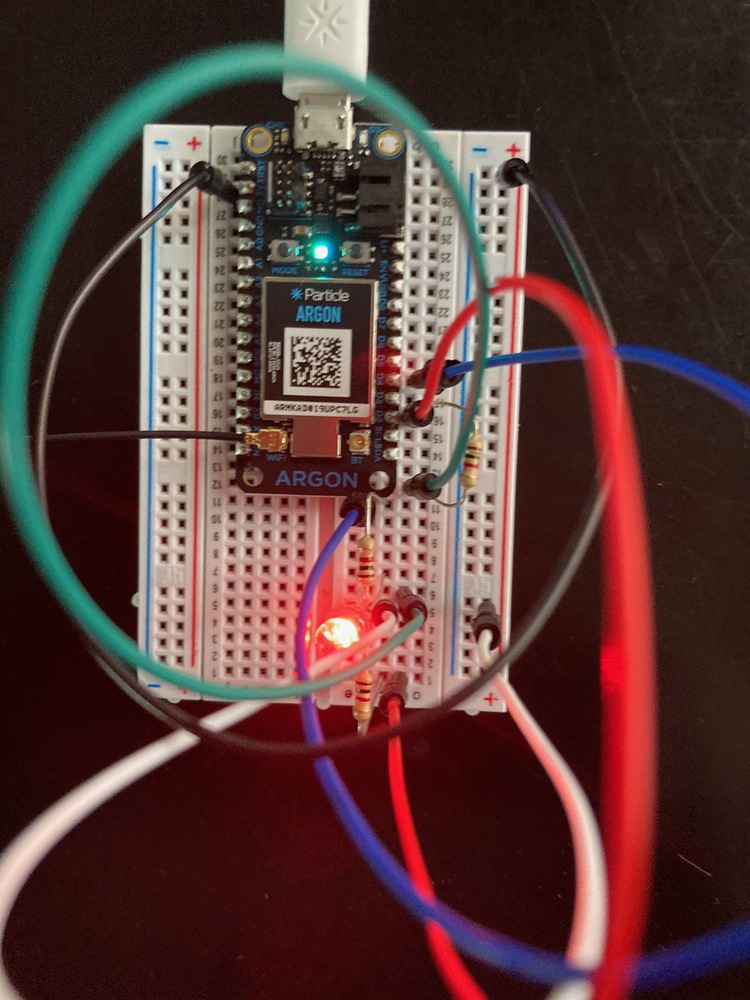
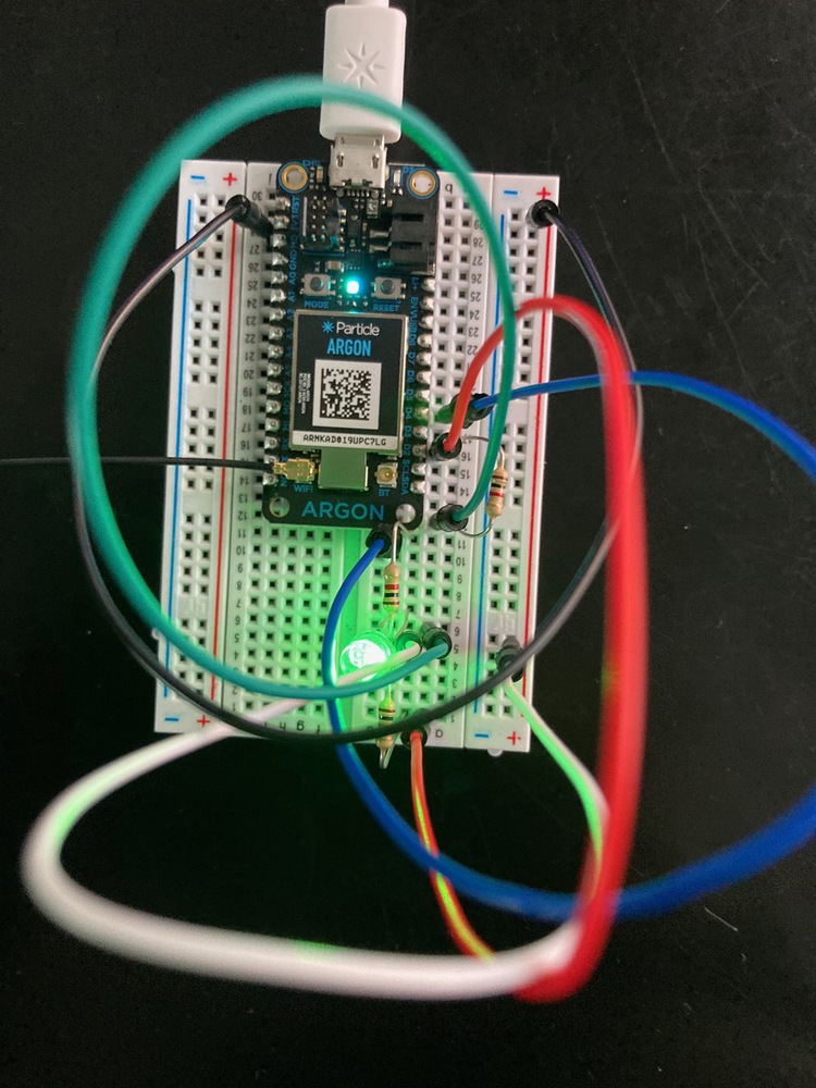
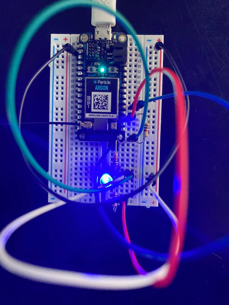
I had to take my time with this since it was my first time using electronics like this as well as using Particle and Gallery. Watching the class presentation was very important for me, but having the written content in the tutorial was also valuable since it explained in a different way what was going on with the pieces. I feel okay about the setup, but need to see if I could do it again without any guidance to really say I understand what is happening.
//Declare variable ledPin as an integer
//Set ledPinI to D2 on argon

int ledPin = D2;
//setup is called once every time a program is run
void setup() {

    //tell argon to use D2 as the output pin
    pinMode(ledPin, OUTPUT);

}

void loop() {
    //turns pin on
    digitalWrite(ledPin, HIGH);
    //for 3000 milliseconds
    delay(3000);
    //turns pin off
    digitalWrite(ledPin, LOW);
    //for 3000 milliseconds
    delay(3000);

    //repeats loop


}//Declare variable ledPin as an integer
//Set ledPinI to D2 on argon
int ledPin = D2;
//setup is called once every time a program is run
void setup() {
//tell argon to use D2 as the output pin
pinMode(ledPin, OUTPUT);
}
void loop() {
//turns pin on
digitalWrite(ledPin, HIGH);
//for 500 milliseconds
delay(500);
//turns pin off
digitalWrite(ledPin, LOW);
//for 500 milliseconds
delay(500);
//turns pin on
digitalWrite(ledPin, HIGH);
//for 500 milliseconds
delay(500);
//turns pin off
digitalWrite(ledPin, LOW);
//for 500 milliseconds
delay(500);
//turns pin on
digitalWrite(ledPin, HIGH);
//for 500 milliseconds
delay(500);
//turns pin off
digitalWrite(ledPin, LOW);
//for 500 milliseconds
delay(500);
//turns pin on
digitalWrite(ledPin, HIGH);
//for 500 milliseconds
delay(500);
//turns pin off
digitalWrite(ledPin, LOW);
//for 500 milliseconds
delay(500);
//turns pin on
digitalWrite(ledPin, HIGH);
//for 500 milliseconds
delay(500);
//turns pin off
digitalWrite(ledPin, LOW);
//for 500 milliseconds
delay(500);
//for 3000 milliseconds
delay(3000);
//repeats loop
}//Declare variable ledPin as an integer
//Set ledPin to D2 on argon
int ledPin = D2;
//Set ledPin2 to D4 on argon
int ledPin2 = D4;
//setup is called once every time a program is run
void setup() {
//tell argon to use D2 as an output pin
pinMode(ledPin, OUTPUT);
//tell argon to use D4 as an output pin
pinMode(ledPin2, OUTPUT);
}
void loop() {
//turns pin (red) on
digitalWrite(ledPin, HIGH);
//for 1000 milliseconds
delay(1000);
//turns pin (red) off
digitalWrite(ledPin, LOW);
//for 1000 milliseconds
delay(1000);
//turns pin (blue) on
digitalWrite(ledPin2, HIGH);
//for 1000 milliseconds
delay(1000);
//turns pin (blue) off
digitalWrite(ledPin2, LOW);
//for 1000 milliseconds
delay(1000);
//repeats loop
}//Declare variable ledPin as an integer
//Set ledPinI to D2 on argon
int ledPin = D2;
// Create a variable to store the brightness of the LED
int ledValue = 0;
//setup is called once every time a program is run
void setup() {
//Register Particle function to allow control of the LED
Particle.function("led", ledControl);
// Make the variable 'ledValue' available through the Particle cloud as 'brightness'
Particle.variable("brightness", ledValue);
//tell argon to use D2 as the output pin
pinMode(ledPin, OUTPUT);
}
void loop() {
// nothinIg to do here since the internet connected funtion above takes over
}
int ledControl(String command)
{
// Convert the passed variable to an integer
ledValue = command.toInt();
// Check it is a valid number
if( ledValue > 255 ) return -1;
if( ledValue < 0 ) return -1;
// Use PWM to set the brightness
// of the LED
analogWrite(ledPin, ledValue);
// Return 1 to say completed successfully
return 1;
}nt redPin = D2; // RED pin of the LED to PWM pin **A4**
int greenPin = D3; // GREEN pin of the LED to PWM pin **D0**
int bluePin = D4; // BLUE pin of the LED to PWM pin **D1**
int redValue = 255; // Full brightness for an Cathode RGB LED is 0, and off 255
int greenValue = 255; // Full brightness for an Cathode RGB LED is 0, and off 255
int blueValue = 255; // Full brightness for an Cathode RGB LED is 0, and off 255
void setup() {
// Set up our pins for output
pinMode( redPin, OUTPUT);
pinMode( greenPin, OUTPUT);
pinMode( bluePin, OUTPUT);
//Register our Particle function here
Particle.function("led", ledControl);
// turn them all off...
analogWrite( redPin, redValue);
analogWrite( greenPin, greenValue);
analogWrite( bluePin, blueValue);
}
void loop() {
// Nothing to do here
}
int ledControl( String command )
{
String colors[3];
colors[0]="";
colors[1]="";
colors[2]="";
int index = 0;
for( int i = 0; i < command.length(); i++ )
{
if( index < 3 ){
char c = command.charAt(i);
colors[index] += c;
if( c == ',') index++;
}
}
// get the red component...
redValue = colors[0].toInt();
// now green
greenValue = colors[1].toInt();
// now blue
blueValue = colors[2].toInt();
// write the mixed color
analogWrite( redPin, redValue);
analogWrite( greenPin, greenValue);
analogWrite( bluePin, blueValue);
return 1;
}