earduino
Made by Alex Alspach
Made by Alex Alspach
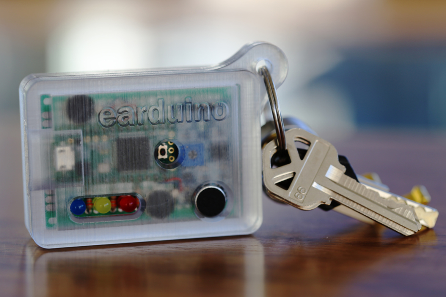
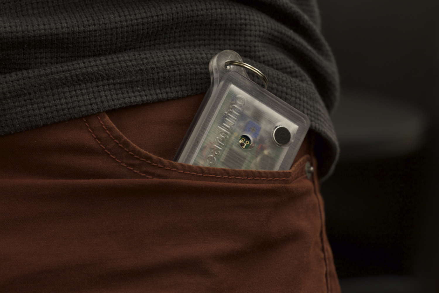
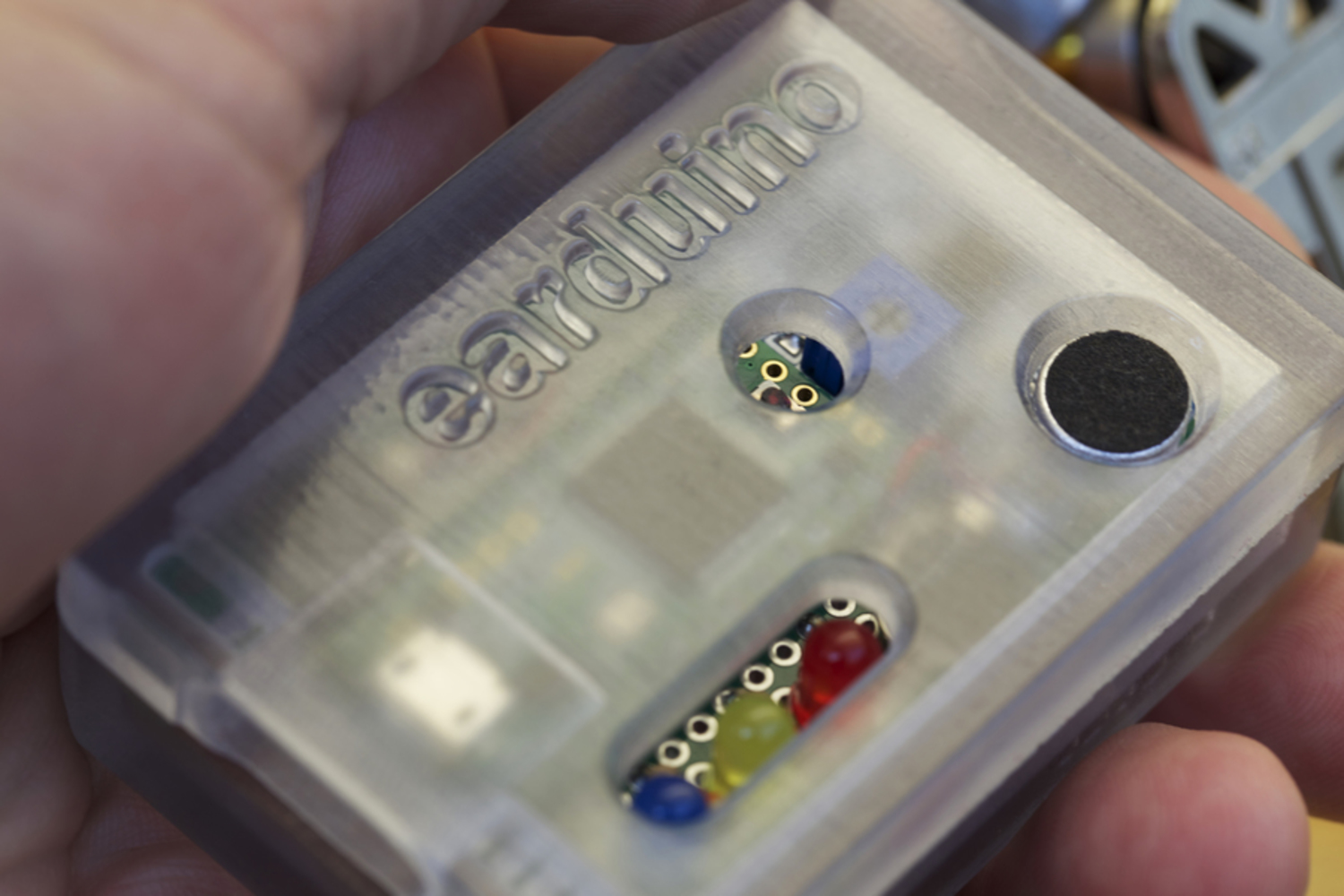
The earduino is a pocket-sized hearing loss prevention device that warns users and bystanders of harmful volume levels by flashing and vibrating.
Created: September 17th, 2015
The earduino is a pocket-sized hearing loss prevention device that warns users and bystanders of harmful volume levels by flashing and vibrating. This project was completed as a part of the "Making Things Interactive" course with Instr. Jake Marisco at CMU in Fall, 2015. This device can be used by frequent concert goers, musicians, constructions workers, drag racers and anyone else who wants to protect their ears from harmful sound levels. Further, a device such as this could be used by the hearing impaired, allowing them to feel and be alerted by loud sounds that they might otherwise miss.
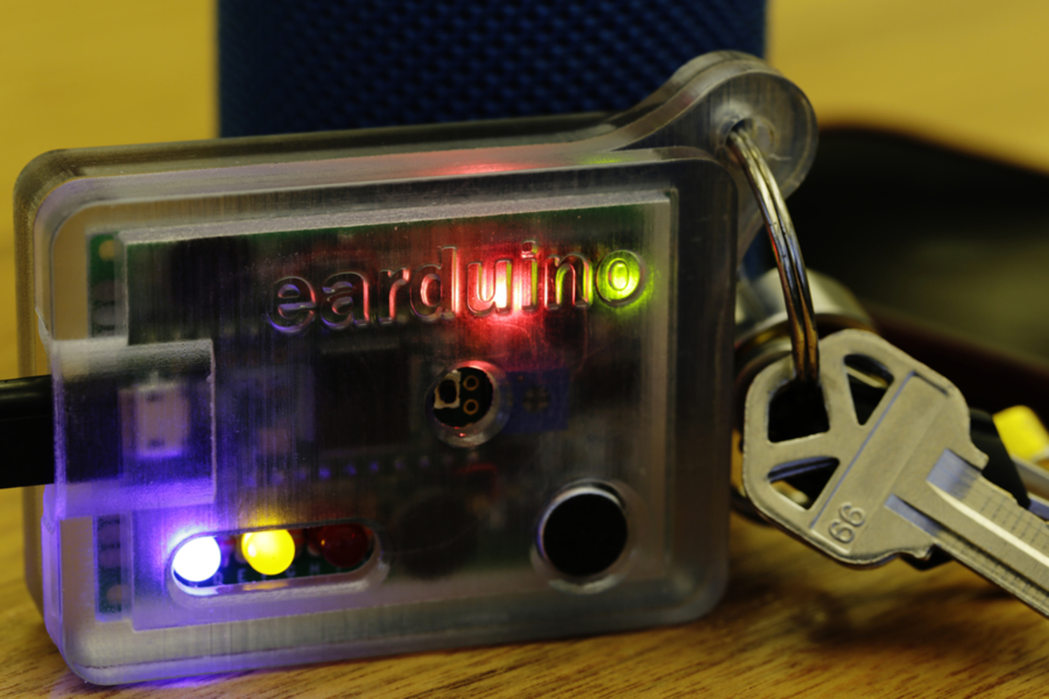
LED colors, brightness and blinking patterns indicate safe and dangerous listening levels.
Safe listening. Whether you're rocking out or rock mining, a steady blue light indicates a safe ambient volume. As the volume increases, so does the brightness.
Too loud. Pulsing blue and yellow lights warn the user to turn down or use hearing protection. Frequency and brightness increase as the ambient volume gets closer to dangerous levels.
Danger zone. If the flashing lights don't bother you, dueling vibrations will warn you of unsafe volume levels. Vibration intensity and frequency increase with volume.
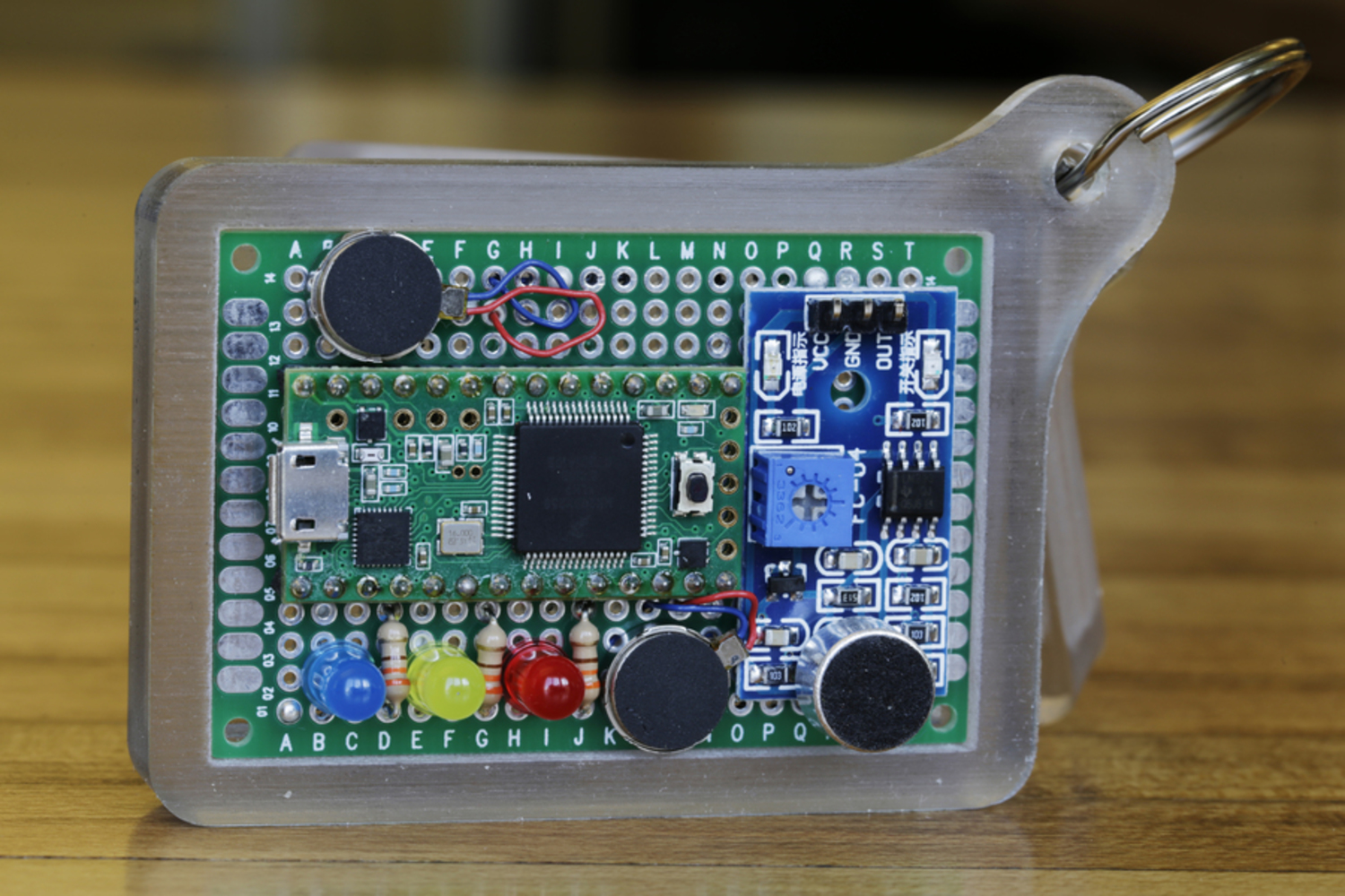
While the name earduino implies that this project is based on an Arduino, the device actually uses a Teensy 3.1 to think. An Arduino Uno was used for prototyping, but was swapped with a Teensy so that it could fit in a pocket-sized package. Using Teensyduino, an add-on for the regular Arduino IDE, it's easy to compile and run an Arduino sketch on a Teensy.
The intensity of each LED and their choreographed pulsing and blinking patterns are controlled using PWM. The waves that drive these PWM values are sine and step functions that can be seen at the end of the following code. These functions take the oscillation period and wave amplitude, as well as phase for inputs. The outputs vales of these functions are mapped to the LED PWM input values, thus controlling the brightness of each LED. The phase argument in each function allows similar waves to be generated out of phase to create patterns like alternating or consecutive pulses and flashes.
Code Overview:
As can be seen in the code below, the first step is reading the signal produced by the microphone using the Teensy's analog to digital converter (ADC). This data is smoothed by taking an average of the most recent 4000 data points. This large averaging window prevents the earduino from reacting to quickly to spikes in the ambient volume. Instead, the average ambient volume over the last second or two affects the output of the earduino.
This average value is then compared to a couple of values which represent the volume thresholds at which "safe listening" becomes "too loud" and when "too loud" becomes dangerous.
In "safe listening" mode, or mode 1, only the blue LED is lit. The intensity or the sensed sound is mapped to the PWM duty cycle controlling the LED. The steadily lit LED therefore becomes brighter as the volume gets louder, until the threshold at the upper limit of safe listening is reached. In mode 2, alternating blue and yellow pulsing lights warn the user that they should either turn down the volume or use hearing protection. In this mode, the intensity of the sound drives both the frequency and amplitude, or pulse speed and brightness, of the sine waves displayed by the two LEDs. In mode three, all three lights, including the red light, are lit consecutively and repeatedly. Here, instead of a sine wave, a square wave is used to convey more urgency with more abrupt flashing. Again, the volume is mapped to the blinking frequency and brightness of the lights, as well as the frequency and intensity of pulsing vibrations.
/*
Author: Alex Alspach
Date: 09/18/15
Title: earduino_making_things_interactive_2015.ino
Description: Microphone sampling and LED PWM output for
  earduino: a pocket-sized hearing loss prevention device,
  Making Things Interactive, CMU, Fall 2015
*/


const boolean DEBUG = false; // If true, the mic value can be input by Serial comm. Mic value not used.
const boolean BUZZERS = true; // if false, buzzers will not vibrate
const boolean SHOW = false; // if true, the mic value will run from 0-1023 over the course of about a minute. Mic value not used.

const boolean PRINT_LEDS = false; // If true, LED PWM values will print to serial

float seconds = 0.0; // time counted in seconds from the beginning of the program

// For controlling device over serial.
float controlValue = 0.0; // Takes place of the mic raw data when debugging

// Pin numbers
int led1 = 3;
int led2 = 4;
int led3 = 5;
int micPin = 7;
int vibePinOne = 23;
int vibePinTwo = 22;

// Buzzer Parameters
float vibeMin = 50.0; // Lowest PWM value that I can feel
float vibeMax = 255.0; // Max vibration PWM value
float vibeAmp = (vibeMax - vibeMin) / 2.0; // Sine wave amplitube
float vibeCenter = vibeMin + vibeAmp; // Sine wave center

// MIC Parameters
float micMin = 0.0;
float micMax = 1023.0; //1023 actual max (Lower number maxes max volume lower

// LED Parameters
float ledMin = 0.0;
float ledMax = 255.0;


// PWM values for buzzers
float vibeCommandOne = 0.0;
float vibeCommandTwo = 0.0;

// PWM values for LEDs
float tempVal = 0.0;
float led1Val = 0.0;
float led2Val = 0.0;
float led3Val = 0.0;

// Mic value thresholds that determine which mode we are in: Safe, Warning, Danger
float threshOne = 340.0;
float threshTwo = 680.0;
// Overlap between modes. Not used
float overlap = 0.0;
// Mic value from ADC
float micRaw = 0.0;
// Which mode, 1 (safe), 2 (warning), 3 (Dangerous)
int mode = 0;

// Filtering
// How many samples are taken into the average
const unsigned long windowSize = 4000;
// Data stored here for averaging
float data[windowSize];
// Used for moving average
float total = 0.0;
float average = 0.0;
int dataIndex = 0;


void setup() {

  //setTime(0);

  // Microphone analog input
  pinMode( micPin, INPUT );

  // LED PWM output
  pinMode( led1, OUTPUT );
  pinMode( led2, OUTPUT );
  pinMode( led3, OUTPUT );

  // Buzzer PWM output
  pinMode( vibePinOne, OUTPUT );
  pinMode( vibePinTwo, OUTPUT );

  Serial.begin(9600);

  // Fill up the data array with zeros before we start gathering data
  for (int thisReading = 0; thisReading < windowSize; thisReading++)
    data[thisReading] = 0;
}

void loop() {


  // keep time in seconds
  seconds = millis() * 0.001;

  // If in debugging mode, the value obtained via serial is used as the microphone signal
  // The average is also updated immediately to produce an immediate state change in the device
  if ( DEBUG == true ) {
    if (Serial.available() > 0) {
      // read the incoming integer
      controlValue = Serial.parseInt();
      // say what you got:
      Serial.println(controlValue);
      micRaw = controlValue;
      average = controlValue;
    }
  }

  // If in show mode, the full microphone signal range is linearly traversed,
  // producing the full range of device output states
  if (SHOW == true) {
    if ((millis() % 50) == 0 ) micRaw += 1.0; //50
    if ( micRaw > micMax ) {
      micRaw = 0.0;
      average = 0.0;
    }
  }

  // Read the mic via the ADC when not in debugging or show mode
  if ( DEBUG == false && SHOW == false) {
    micRaw = analogRead(micPin);
  }

  // See movingAverage function at bottom of code
  average = movingAverage();
  delay(1);


  // Which Mode are we in (1-3: Safe, Warning, Danger)
  mode = 0;

  // Reset LED PWM values to Zero
  led1Val = 0.0;
  led2Val = 0.0;
  led3Val = 0.0;


  // First Range, Safe Range, Mode1
  if ( (average >= micMin) && (average < threshOne) )
  {
    tempVal = mapfloat(average, micMin, threshOne, ledMin, ledMax);
    if (tempVal < ledMin) tempVal = ledMin;
    if (tempVal > ledMax) tempVal = ledMax;
    led1Val = tempVal;
    mode = 1;
  }

  // Second Range, Warning Range, Mode2
  if ( (average >= (threshOne - overlap) ) && (average < threshTwo) )
  {
    tempVal = mapfloat(average, (threshOne - overlap), threshTwo, ledMin, ledMax);
    if (tempVal < ledMin) tempVal = ledMin;
    if (tempVal > ledMax) tempVal = ledMax;
    led2Val = tempVal;

    if (average >= threshOne) mode = 2;
  }

  // Third Range, Danger Range, Mode3
  if ( (average >= (threshTwo - overlap) ) && (average <= micMax ) )
  {
    tempVal = mapfloat(average, (threshTwo - overlap), micMax, ledMin, ledMax);
    if (tempVal < ledMin) tempVal = ledMin;
    if (tempVal > ledMax) tempVal = ledMax;
    led3Val = tempVal;

    if (average >= threshTwo) mode = 3;
  }


  // First Range, Safe Range, Mode1
  if (mode == 1) {

    vibeCommandOne = 0;
    vibeCommandTwo = 0;
  }

  // Second Range, Warning Range, Mode2
  if (mode == 2) {

    float wavePeriod = mapfloat(led2Val, 0.0, 255.0, 3.0, 1.0);

    led1Val = sinWave(wavePeriod, PI, led2Val / 2, led2Val / 2);
    led2Val = sinWave(wavePeriod, 0.0, led2Val / 2, led2Val / 2);

    vibeCommandOne = 0.0;
    vibeCommandTwo = 0.0;

    //Serial.println(wavePeriod);

  }

  // Third Range, Danger Range, Mode3
  if (mode == 3) {

    float wavePeriod = mapfloat(led3Val, 0.0, 255.0, 2.0, 1.0);

    led1Val = squareWave(wavePeriod / 1.0, PI, led3Val);
    led2Val = squareWave(wavePeriod / 1.0, PI / 2.0, led3Val);
    led3Val = squareWave(wavePeriod / 1.0, 0.0, led3Val);

    vibeCommandOne = sinWave(wavePeriod / 2.0, 0.0, vibeCenter, vibeAmp);
    vibeCommandTwo = sinWave(wavePeriod / 2.0, PI, vibeCenter, vibeAmp);

    //Serial.println(wavePeriod);
  }


  // LED PWM Control! // ~~~~~~~~
  analogWrite( led1, led1Val );
  analogWrite( led2, led2Val );
  analogWrite( led3, led3Val );

  // Buzzers! // ~~~~~~~~

  // For debugging you can turn the buzzers off for sanity
  if (BUZZERS == false) {
    vibeCommandOne = 0;
    vibeCommandTwo = 0;
  }

  // Thresholding the PWM input values
  if (vibeCommandOne < 0) vibeCommandOne = 0;
  if (vibeCommandOne > vibeMax) vibeCommandOne = vibeMax;

  // Buzzer PWM Control
  analogWrite(vibePinOne, vibeCommandOne);
  analogWrite(vibePinTwo, vibeCommandTwo);


  Serial.println(average);

  if (PRINT_LEDS == true ) {
    Serial.print(average);
    Serial.print("\t");
    Serial.print(led1Val);
    Serial.print("\t");
    Serial.print(led2Val);
    Serial.print("\t");
    Serial.print(led3Val);
    Serial.print("\n");
  }

}


float sinWave(float period, float phase, float center, float amplitude) {

  //float period = 1.0;
  float frequency = 1 / period;
  //float phase = 0;
  float wave = 0.0;
  //Serial.println(seconds);
  return wave =   (sin(seconds * frequency * 1.0 + phase ) * (amplitude) + center); //magic 6.12

}


float squareWave(float period, float phase, float amplitude) {

  if ( period <= 0.001 ) return 0.0;

  int wave = 0;
  int periodMs = period * 1000; //convert to milliseconds
  int phaseMillis = (phase / (2.0 * PI)) * (periodMs);
  int ms = millis() + phaseMillis;

  if ( (ms % periodMs) >= (periodMs / 2) ) wave = amplitude;
  else wave = 0;

  return wave;

}

float movingAverage() {

  total = total - data[dataIndex];
  data[dataIndex] = micRaw;
  total = total + data[dataIndex];
  dataIndex = dataIndex + 1;

  if (dataIndex >= windowSize)
    dataIndex = 0;

  return ( total / windowSize );

}

float mapfloat(float x, float in_min, float in_max, float out_min, float out_max)
{
  // Modified version of skumlerud's function from
  // http://forum.arduino.cc/index.php?topic=3922.0
  return (float)(x - in_min) * (out_max - out_min) / (float)(in_max - in_min) + out_min;
}Making Things Interactive (MTI) is a studio course based on physical prototyping and computing. You will develop novel sensing, interaction and display techniques through projects and short assignm...more
The earduino is a pocket-sized hearing loss prevention device that warns users and bystanders of harmful volume levels by flashing and vibrating.