Locking Sketchbook
Made by Jett V.
Made by Jett V.
Final project for 15-294: Rapid Prototyping Technologies (F15), in which we should design and fabricate something interesting that utilizes some of the prototyping processes taught in class.
Created: March 25th, 2016
For the 15-294 F15 final project, I designed and built a sketchbook with a gear-based locking mechanism from scratch (save for bought materials such as wood, paper, etc.).
Link to course website: http://www.cs.cmu.edu/afs/cs/academic/class/15294-f15/index.html
The goal of this project was to utilize one or more of the rapid prototyping processes to create an object that has an interesting aspect, possibly: Solidworks features such as parametrized equations or reference geometry, some of the construction techniques we discussed such as the "dragon's claw" latching technique, or is particularly aesthetically pleasing.
Knowing that we had to use a laser cutter and/or 3D printer, and be able to design at least part of our project using Solidworks, I came up with the following ideas after a discussion with my TA:
I do not really know what really drew me towards the sketchbook idea rather than the desk organizer idea, but a desk organizer was also something that I wanted to make that could be useful in some way. I had to think about what set of tools it should hold (my pencils/pens? Drawing tools such as brushes, coloured pencils, etc? Paper? Shelves for CDs/DVDs or games?). How I would construct it and out of what material---wood gives a nice finish and can be easily glued, and while this and acrylic can be easily screwed together, acrylic is a it more difficult to hold together with glue. Acrylic is also quite nice as far as opaque or transparent/translucent colour possibilities, though wood could also be painted (but then I would have to paint it). I would have made something that could be easily transported between my desks at home and at school, though I could have just as well made multiples.
There were no strong ideas for the laser cut sculpture idea. Though, I did briefly entertain the idea of having it be a puzzle, where the end state is the sculpture. One possibility was making an animal of some sort, perhaps a magical one, but a few other students were already planning on making something animal-related.
At first, I did not consider the sketchbook idea because I thought it would not turn out to be interesting in the least---it is basically a boring, blank book---and kept on brainstorming for other possibilities. Though after running through the ideas again, I figured I could make it interesting by adding extra parts---hopefully moving parts.
Purely because I could not immediately come up with an idea for a story---and I did not want to just use some pre-existing story, though a pop-up interpretation would have been quite cool---I decided not to run with this idea for now. (Though I have always wanted to make one of these!)
It could be because I am a coward, but I decided not to stick with the armour idea because I feared I would not finish it in time because of what would be involved in making it. (I would of course go for the most complicated and intricate idea I could as a challenge, but realistically...)
Deciding upon the sketchbook concept, I thought about what goals I wanted the book to fulfil. In addition to the requirements for the project, I wanted the book to be able to:
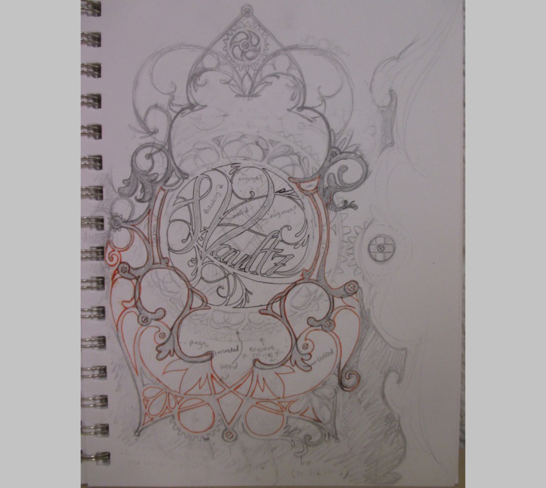
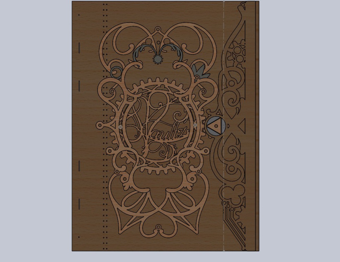
My concept for this book then became one that has a flap attached to the back cover that would wrap around to the front and could be fastened there via a lock of some kind. We'd worked with gears a few times throughout the class thus far, so the first idea to pop into my head was that of a gear-based locking mechanism, rather than some single knob one would turn. I decided to have the gear that people would turn be visible and large and contain a design. The smaller gear would be covered by the flap, atop of which is a shape that rotates with the small gear to hold the flap down in place. To hold the larger gear in place, would be some extra decorations to make the whole piece look a bit more interesting.
I wanted the book to have a somewhat flexible yet rigid cover, but nothing fragile, though it should not be able to bend in half easily. The usual backboard for sketchbooks seemed like the best idea, as opposed to wood, which was my first thought. The decorations and lock should be in wood, however, because I wanted these to be more rigid and have a different colour from the cover boards. Any additional and smaller decorations could be in a thick cardstock, so as to not have each layer be so thick---it would not be ideal to have the parts on the cover sit half an inch above the surface. 1/8" thick parts is already pushing it, but this book could always just be a display piece, as the addition of the decorations make it a bit impractical.
Materials List
I decided to start with making the book block---with binding the pages together---so that I could then determine the dimensions of everything that I would need to make in Solidworks.
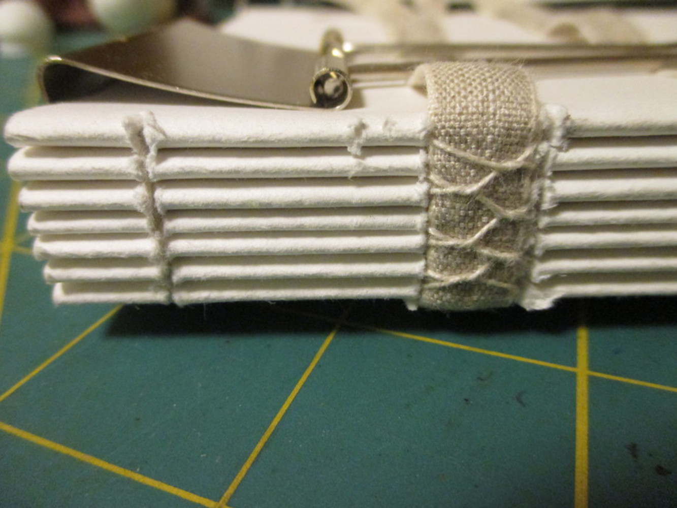
After researching a little on different methods and aspects of bookbinding, I found that a sort of coptic stitch would work best according to my established criterion. Combining that with some improvisation, I created a few sketches on how I wanted the book to look and how each part fits together.
Game Plan
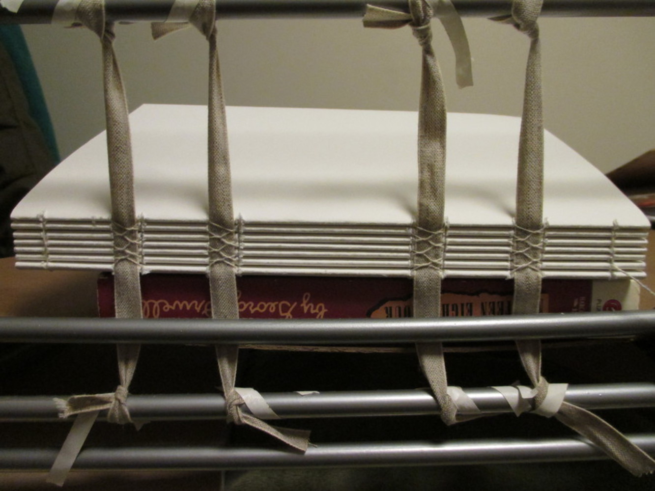
Unlike the professionals, I do not have a bookbinding press, awl, rectangular weights. Though I do have a clothes-drying rack, serrated knife, and a lot of textbooks. I found that using something like an awl would have taken too much time---especially with thicker paper---though a saw or serrated blade has been used by professionals, so it was not like it was unheard of to use such tools in lieu of an awl. In retrospect, the rack was actually a little unnecessary, as this could just as well have been done by hand, although using the rack means less items for me to hold and keep track of at once.
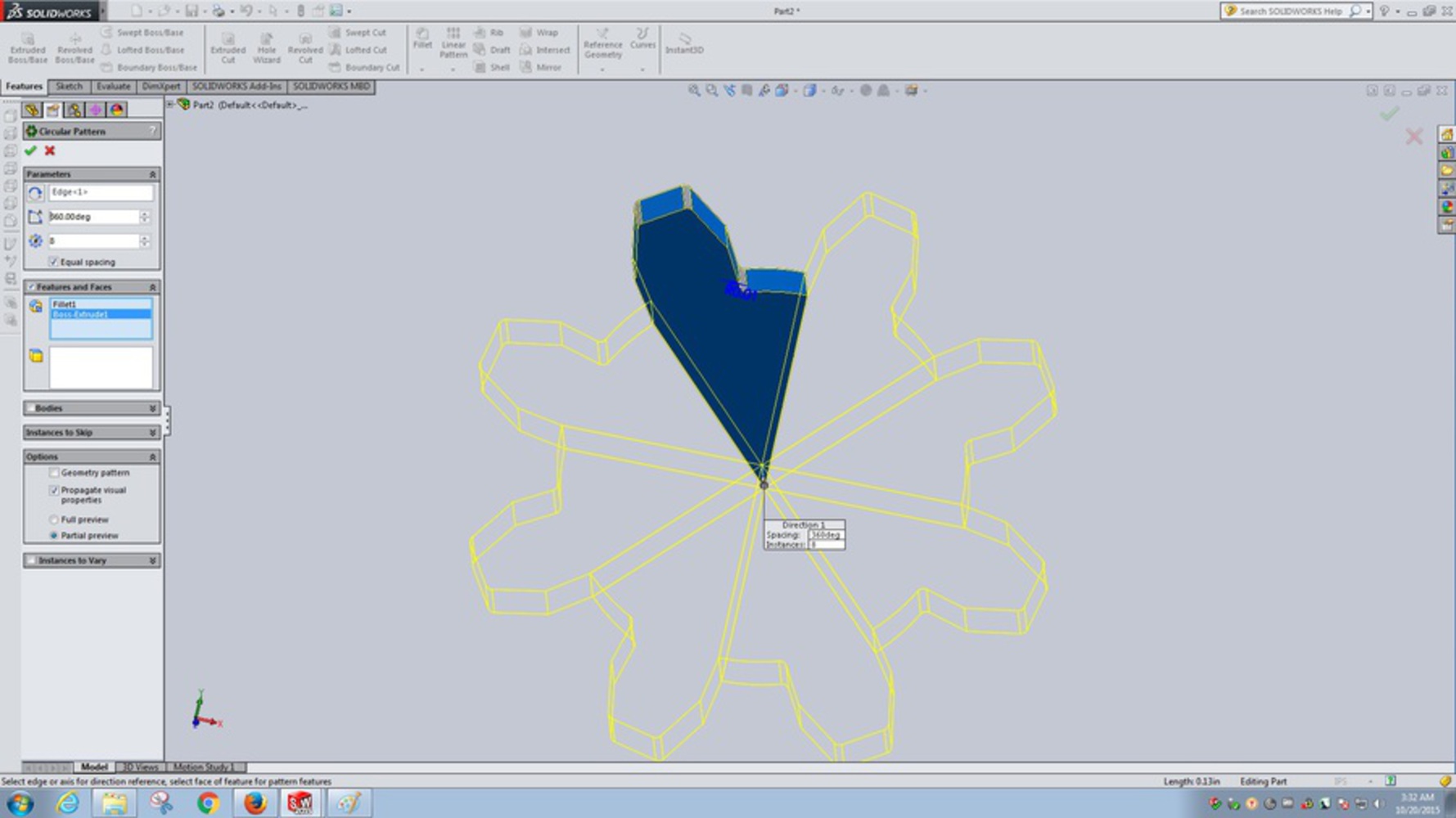
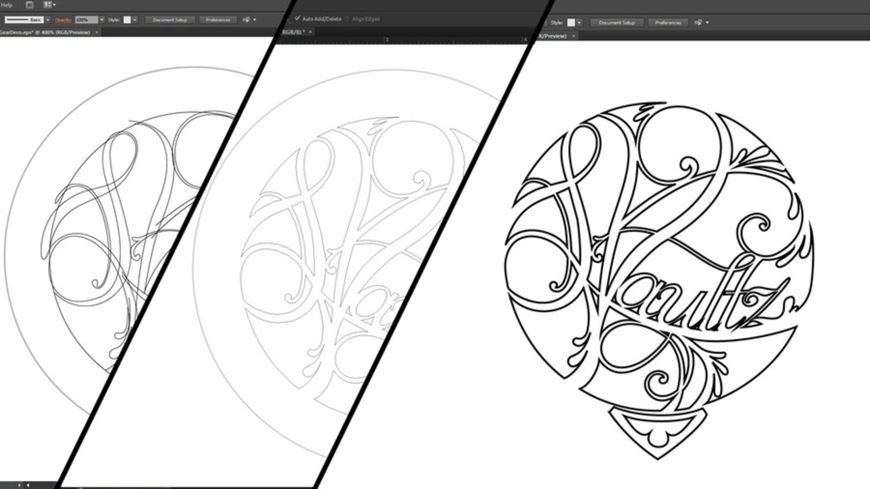
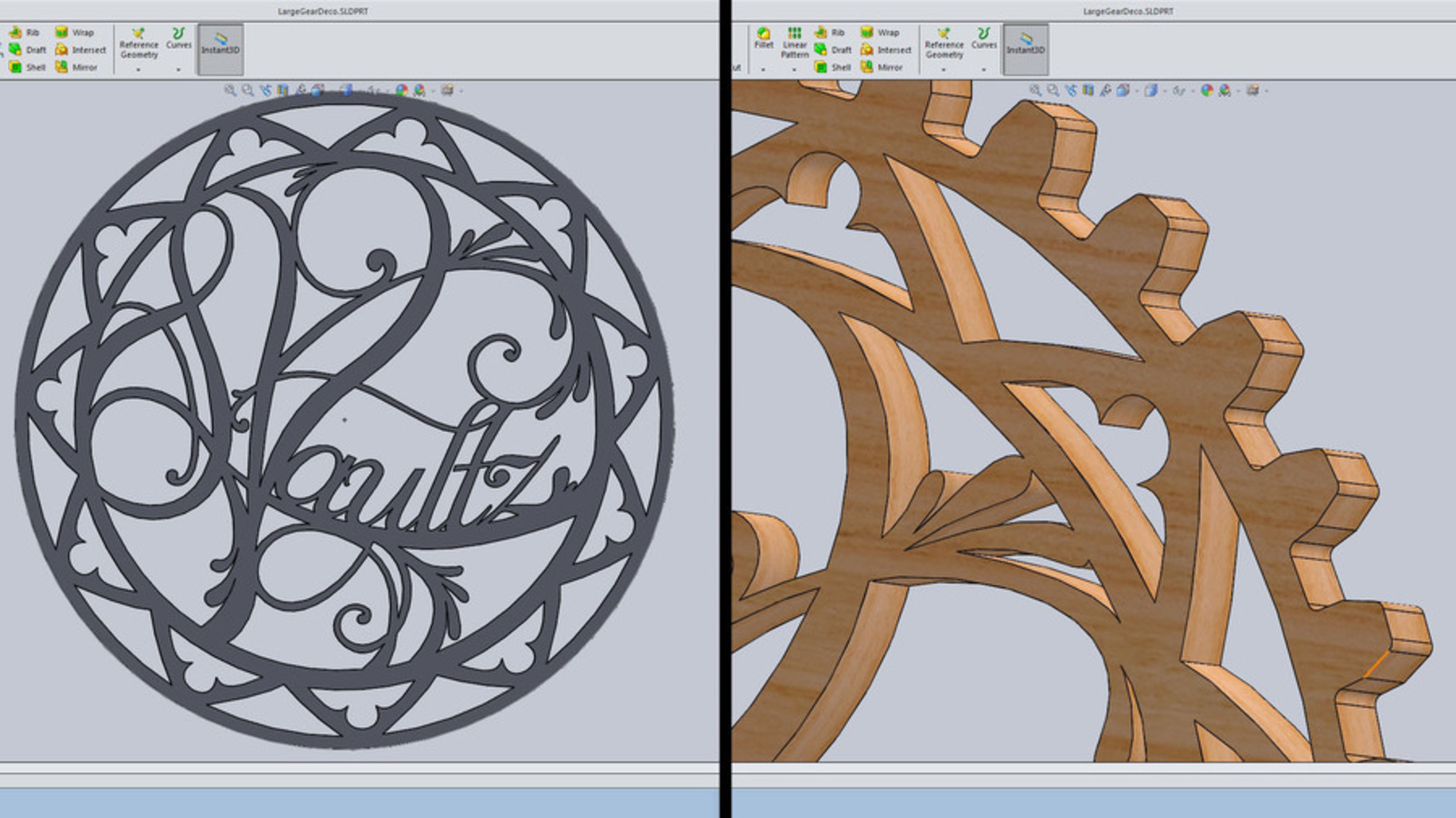
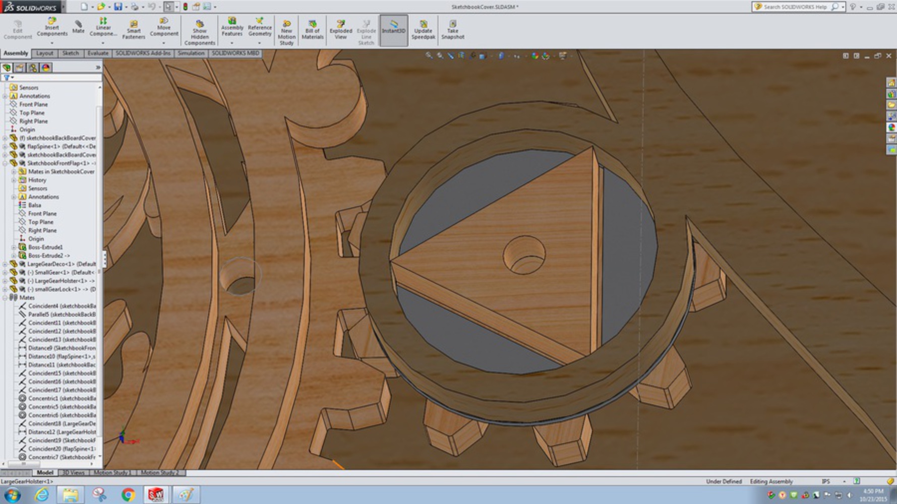
After knowing the dimensions of the larger gear, I sketched out a design for that on paper, then refined it in Illustrator and imported the vectors to Solidworks to make an extruded cut in the large gear part. After making sure there was nothing wrong with the parts, I cut out a prototype of the two gears.
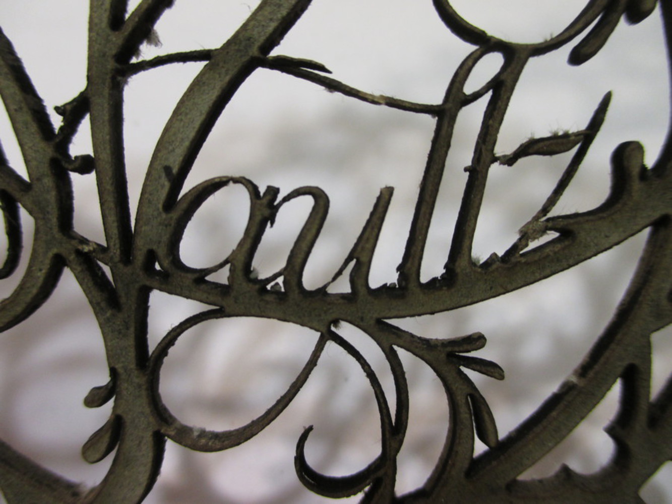
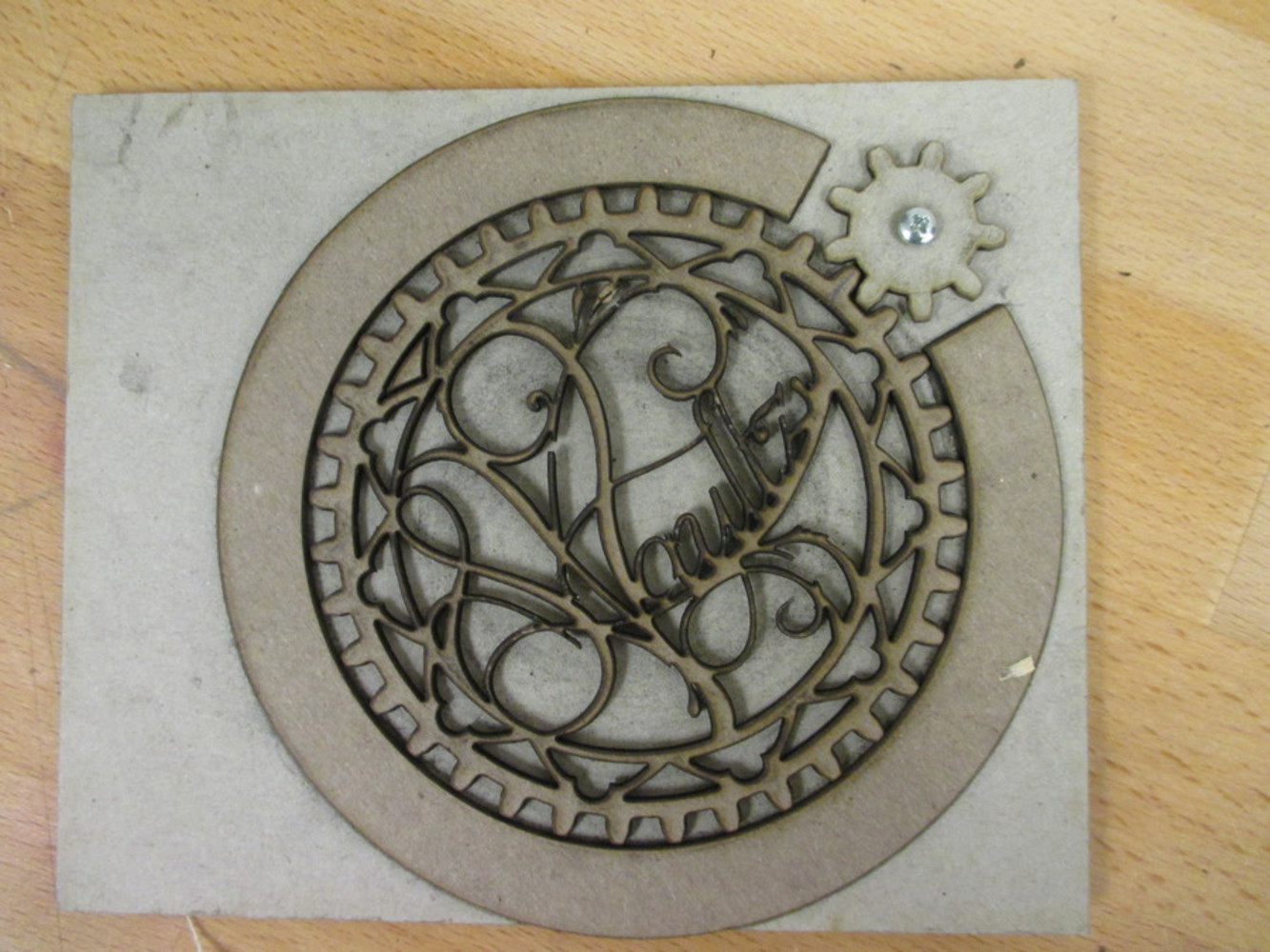
The gears meshed perfectly. However, the design turned out to be too thin, and caused pieces to be unintentionally cut off by the laser cutter as shown in fig 4a. This could also be due to board I was using, though I decided to increase the weight of the lines. After thickening the thin spots, pieces still crumbled away due to the laser, though the resulting design, as cut out in fig 4b, was sturdier and worked much better overall.
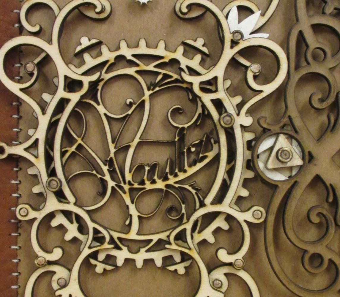
The next step was designing the triangle lock. I wanted something that could simply be rotated to unhook or unlatch the flap. I decided to go with a triangle, as it proved to be the sturdiest for something so small, as opposed to a flat rod with more potential for breaking.
The triangular piece would be attached to the small gear underneath and that whole piece would rotate freely, allowing the larger gear to turn the lock into place. I made a small gap in between the triangle and the small gear, so that a thin piece of card stock could fit underneath and hook triangle in place. A matching triangle would be cut out of the card stock with just enough space to allow the triangle to pass through when rotated to fit.
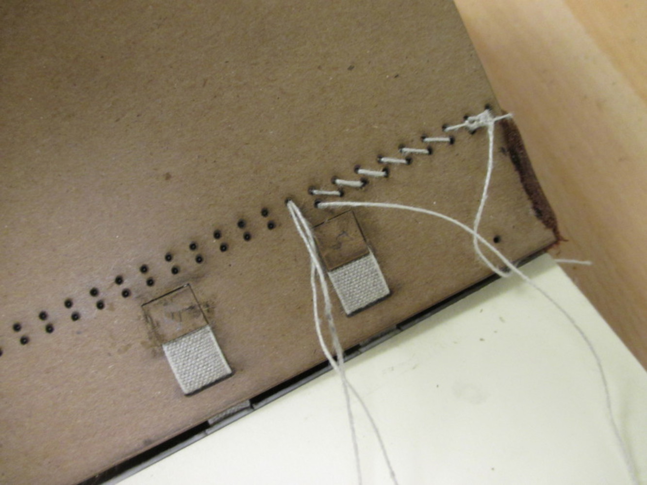
The cloth tapes were going to be glued to the cover boards, so I thought it would be useful to cut out holes and wells to inset the tapes and create a flat surface. Instead of doing so by hand, I decided to add this in to the design for the laser cutter to lightly cut out (not all the way through) the square outlines, and then peel them off afterwards to create the wells.
At this point I made a little mistake when moving my files, and thus I had to redo 80% of all the modelling I had done within a day. I became forcefully reacquainted with the spline tool in Solidworks. As a result, there were some changes made between the model shown in fig 6. above and the final product shown below in fig 9.
I made a few more prototypes to make sure that the parts would fit together, such as the cover boards. I checked to see if the 1/8" dowel did in fact fit in the holes, as well as whether or not I would be able to fit the needle I had through the holes for sewing on the leather. Once that checked out and the files were finalized and .dxf files were generated, I sent everything to the laser cutter and then started assembling the book. I checked to see that the leather still fit before gluing everything together, and it just fit around the spine to the line of holes on the front and back covers (those brilliant planning skills though).
I was not sure at this point whether I should leave the cloth tapes bare as shown in fig 7. though it would not have fit with this particular design, as I still planned on having the wooden pieces on the front cover. I decided to move ahead with adding the leather instead of leaving the spine as it was, even though it also would have been aesthetically pleasing.
Fig 8. above shows how the cover boards are attached, as well as the progress of sewing on the leather. I only then found out that because the board I used in the final product is denser than the board I used as a test, the holes cut by the laser were slightly smaller than they should be. The combination of this and the leather made it ridiculously difficult to get the needle through teach time. There were a lot of holes. Add in the fact that it is difficult to grip something so thin as a needle when a lot of force is required, and the result it much sadness and injury.
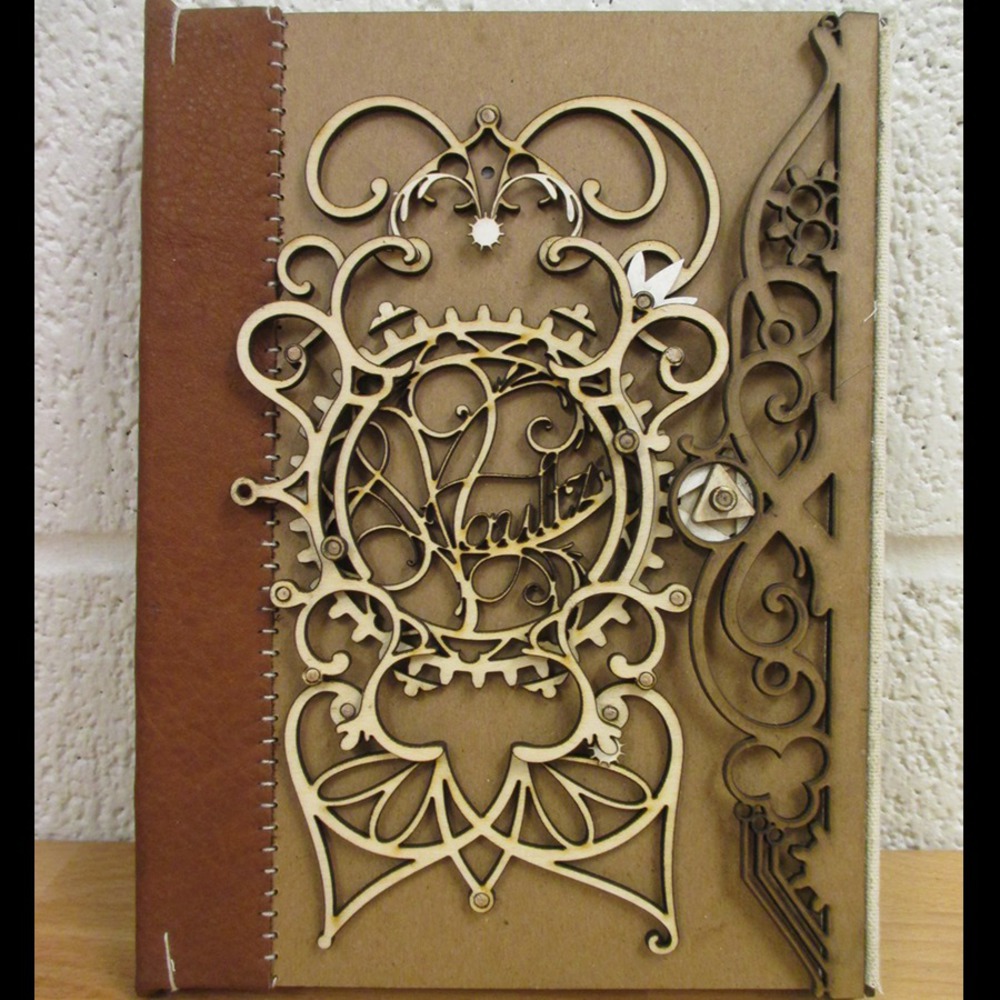
Finished Book
Some hours later, a completed book emerges!
Final dimensions: 9"x6.5"x1.5" including covers, with 9"x6" pages
Construction time: approximately 7 hours in one sitting
Gears: 1:4, 36 teeth on large 3.5" gear and 9 teeth on small 1" gear
Number of pages: 80 pages (40 sheets)
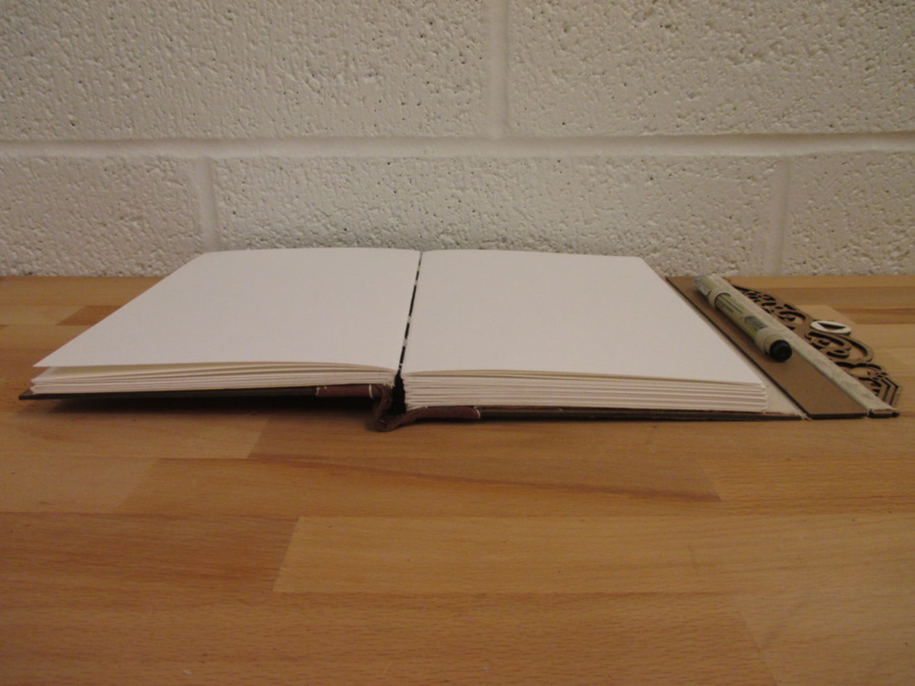
Opening and closing the book is really smooth, and there is no tightness in the spine that restricts the movement. The flap of the book sits rather low, however, so I have to shift it up just a bit so that the triangle fits properly through the hole.
It also still lays flat, as planned, even after all of the additions.
There are a few things I learned throughout this process---aside for learning a piece of the magical art of bookbinding:
While sewing the leather onto the covers, I found that I should have tested the holes for the needle on the same type of board than on a slightly less dense board, as the holes turned out ever so slightly too small. I also found that I just really dislike sewing through leather.
I was too eager to put on the wooden parts to realize that I should have attached the leather first. That was fun...
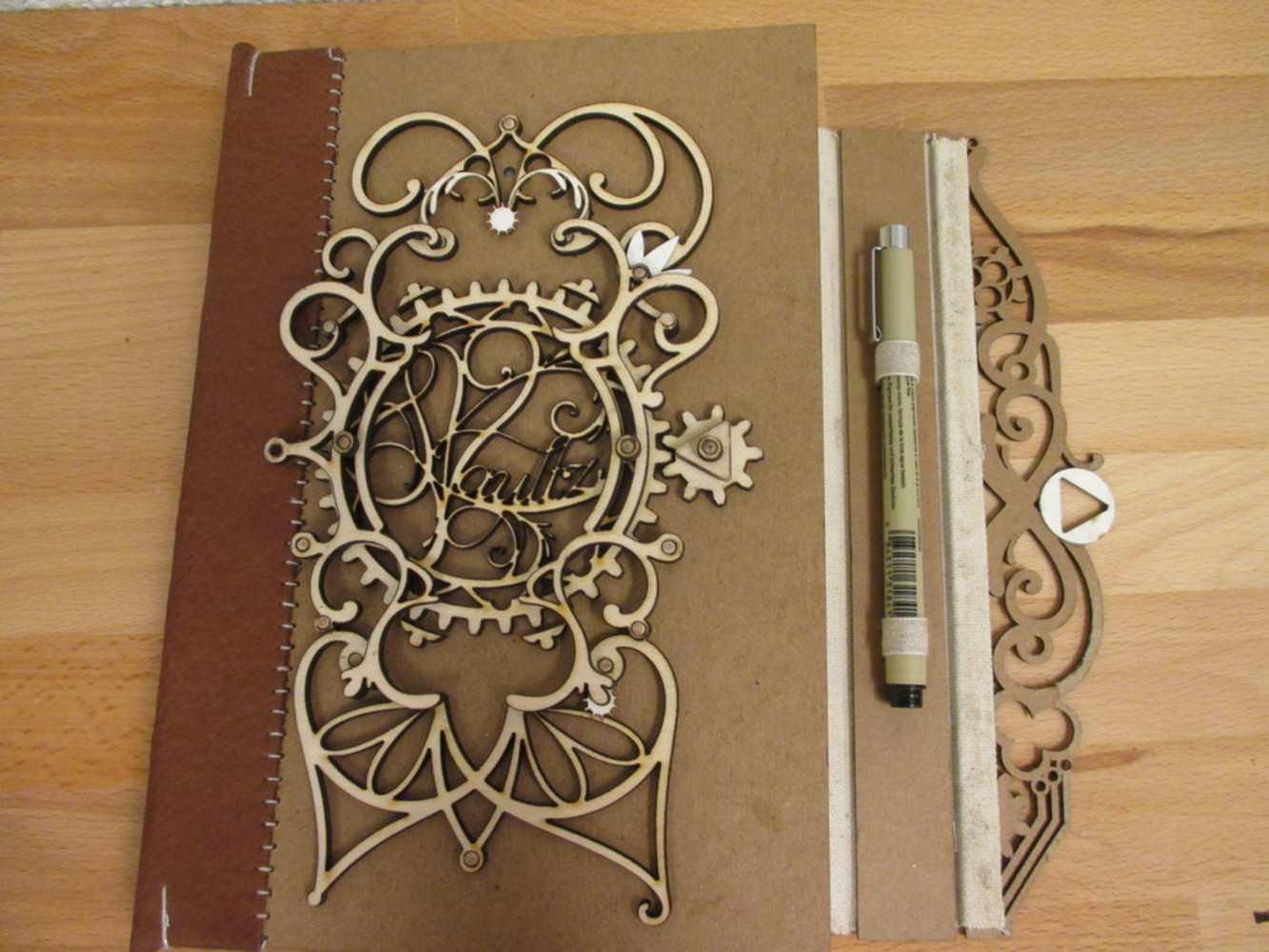
At the time I did not have any elastic for the pen/pencil holder. Instead I used leftover cloth tape, which meant that I had to fit it to a specific pen, and anything thinner would not stay. The glue holds terribly well, so modifying this would be difficult, though not impossible. I would rather have elastic bands so that thinner pens could fit without the need of a hook.
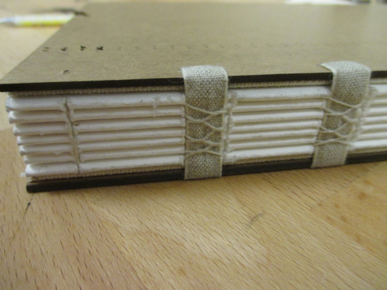
I was not sure at what point I should sew on a header at the top and base of the spine so that the leather would not stick out, as shown in the photo below. It is not that pleasant to look at, and can also become easily scuffed and damaged when the book is being put onto and taken off of a shelf as that extra bit scrapes on the shelf surface. It is really difficult to sew into the leather by hand, and I have injured myself a few times doing so. However, looking back, glue may have sufficed.
When I designed the locking mechanism, my intention was for the larger gear to be turned by rotating it in either direction by holding the teeth that are exposed at the top and bottom. This is why those parts are exposed. I found that when other people tried to open it, about half went straight to the small triangle and tried to rotate that---that would break it, though---the force would be too great for the glue to hold. They seem to do this because they know that this part is what has to be rotated so that the triangle fits through the hole. The rest of the people move to the large gear, and try to move the little knobs on either side in the slots. I guess a side affect of using the ring and dowel to make sure the large gear rotates in place is that they become miniature handles for rotating the gear. The ring atop of the triangle is actually the highest point, so perhaps this indicates to people that this is what they must have a go at first?
Final project for 15-294: Rapid Prototyping Technologies (F15), in which we should design and fabricate something interesting that utilizes some of the prototyping processes taught in class.