Mini Desktop Mill
Made by droof
Made by droof
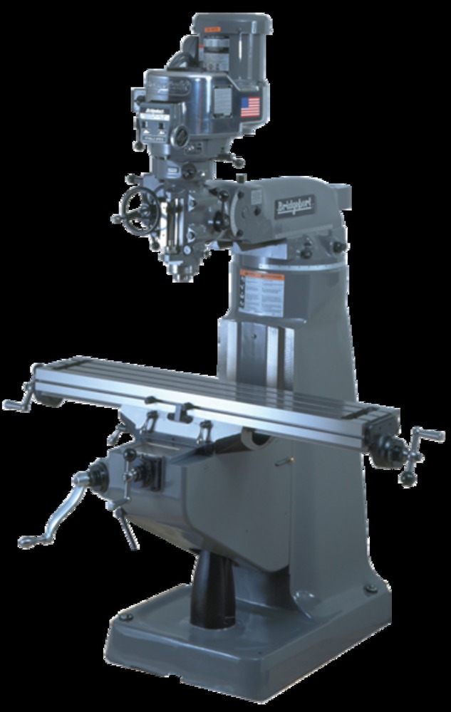
To make a desktop model of a Bridgeport milling machine
Created: May 5th, 2019
I love machining parts. Whether its for a class project, a student organization, or just for me, machining never fails to calm me down. I love the precision I can get out of parts, I love the methodical process needed to succeed, I love the feeling as the cutter removes metal like it's butter, and I love the final look of a perfect part coming out of the vise. However, I do not want to strictly be a machinist for the rest of my life, and I have accepted that I will need some desk and computer time. That is where my mini mill idea came from. I wanted to make a desktop model of a mill that moved just like a real mill, with three axes of motion and a moving spindle. I decided to model it after the Bridgeport milling machine, a classic machine that I've loved working on in the past.
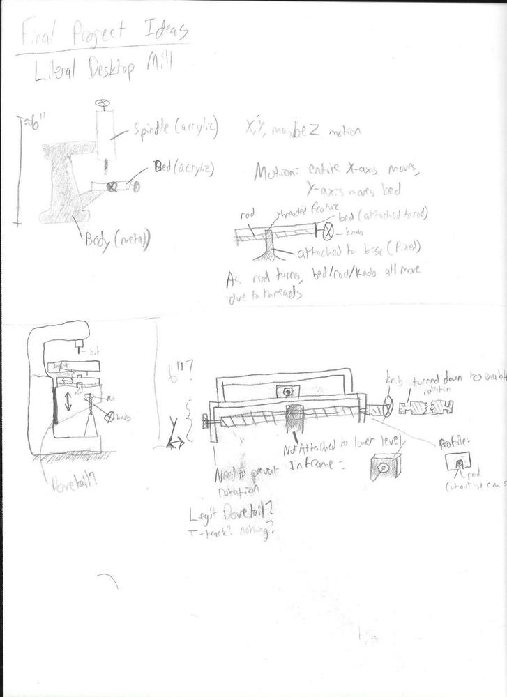
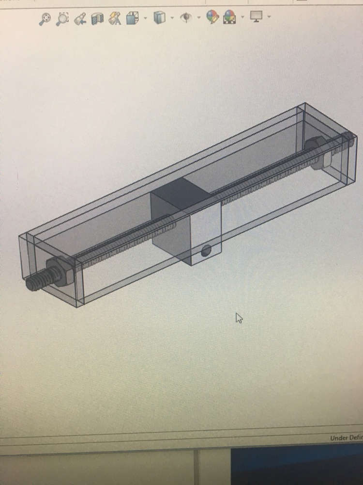
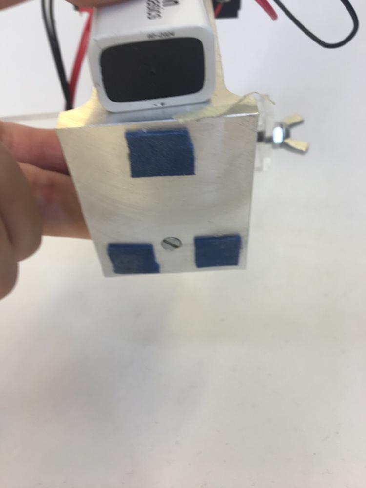
These sketches helped me wok out which axes I wanted to have, how they would move, and what things would generally look like. I decided to use a combination of aluminum and acrylic to make the mill. Machining some parts out of aluminum was both necessary and poetic, since I needed good precision and making parts for my model mill with a real mill amused me. Acrylic could be see-through, which would let people see how the mechanism worked and also allowed for rapid prototyping and adjustments if a design didn't work the first time. My sketch also helped with scale, since when I had a rough sketch of the size I could start putting actual dimensions to the parts. Once I had the ideas down on paper, I could start CADing my mill. I knew I had to use CAD, since making the mill move would require pretty high precision. Making the parts by eye wouldn't work in this case. I had to work out that the x axis would move just the acrylic table, the Y axis would move the table and the rod that moved the X axis, and the Z axis would move the table, the X axis rod, and the Y axis rod. I would use regular 10-32 threaded rod instead of ball or lead screws to save money and make more hardware (like standard tapping tools and nuts) available to use. I started with the table that would move in the X and Y directions, since I was most worried about making that motion work and be reasonably faithful to a real Bridgeport. My first CAD assembly is shown below.
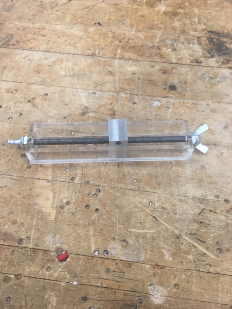
It is a simple box, with each side made out of a single piece of acrylic. The block in the middle had two threaded holes for the X and Y axes. The nuts on the inside of the table walls ensure that when the rod spins, the block moves instead of the rod. In the final construction, when the block would move, the table moves instead since the block is constrained. This transforms the rotational motion of the rod into the linear motion of the table. The same concept moves the Y axis, using the lower hole shown in the block. This block was machined out of aluminum. When gluing it up, some of the acrylic glue spread into the block, staining the table and making for a couple sticky spots. However, it still moves very well in the table.
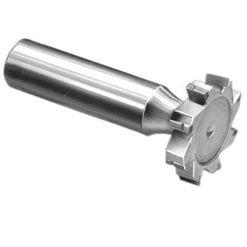
Next up was figuring out the Z motion. As is seen in my initial sketch, I thought I would create movement in the Z axis by moving the spindle instead of the table. However, I moved away from this concept for a couple reasons. One was that when I decided to make the spindle actually spin, I didn't want to worry about making the motor separate from the spinning bit. Also, real Bridgeport mills move the table itself, and when I decided to make the head rotate making the spindle move became basically impossible. Z axis motion was difficult, since they usually move in dovetail slots like shown below.
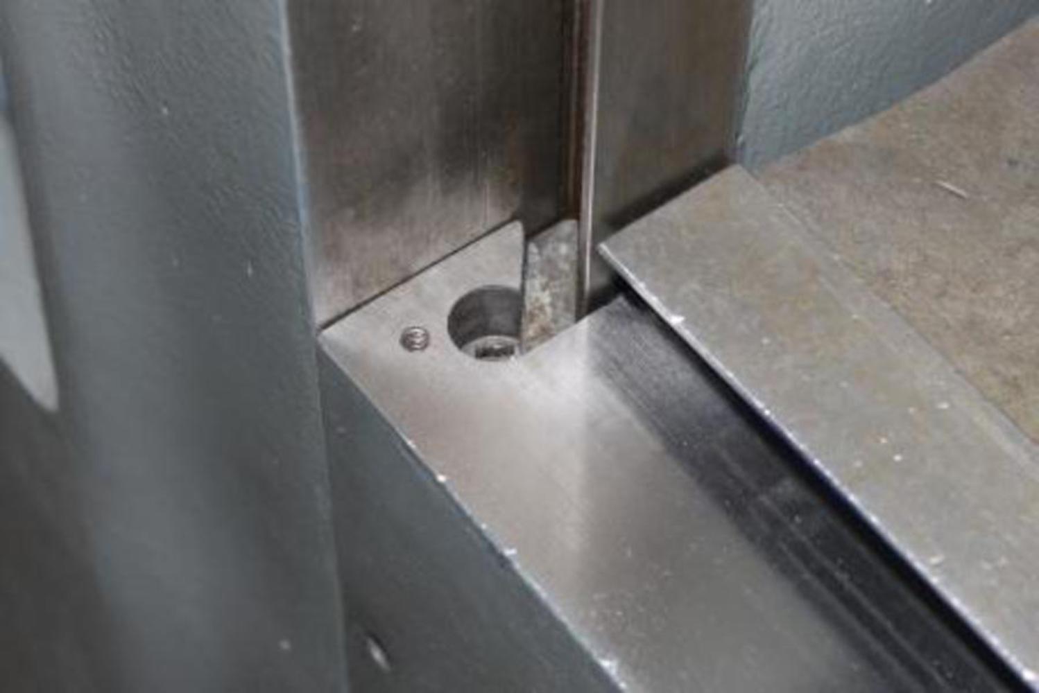
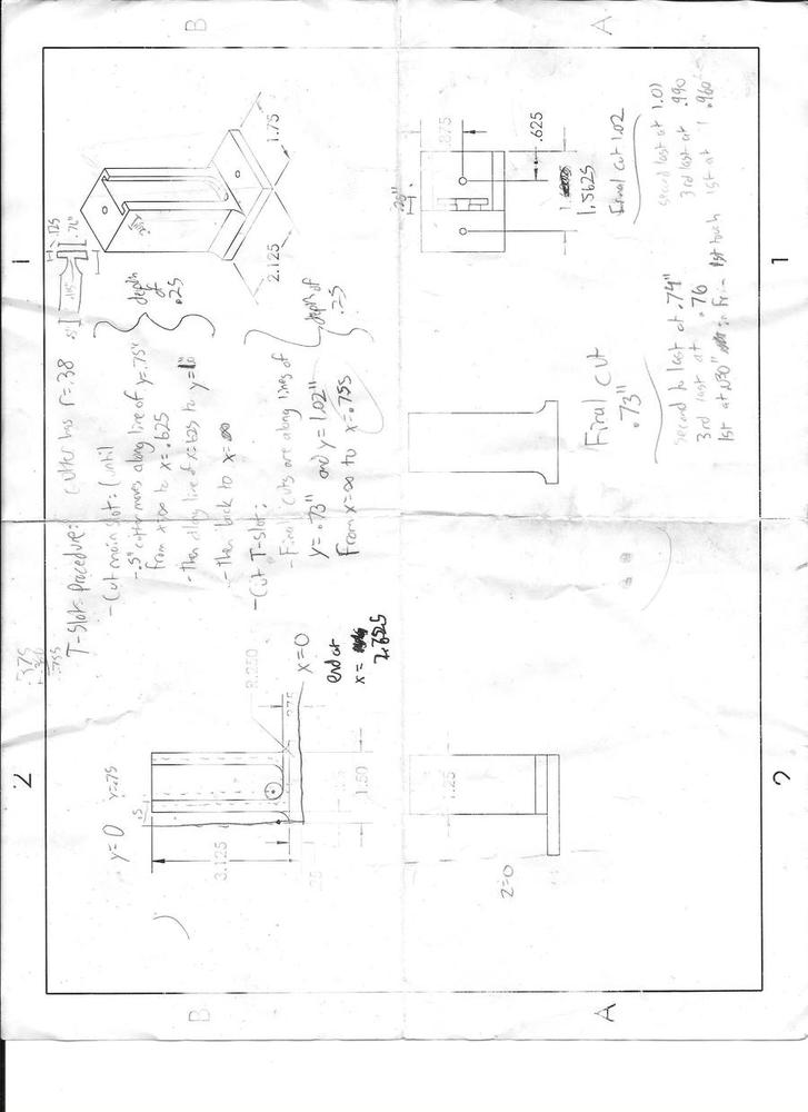
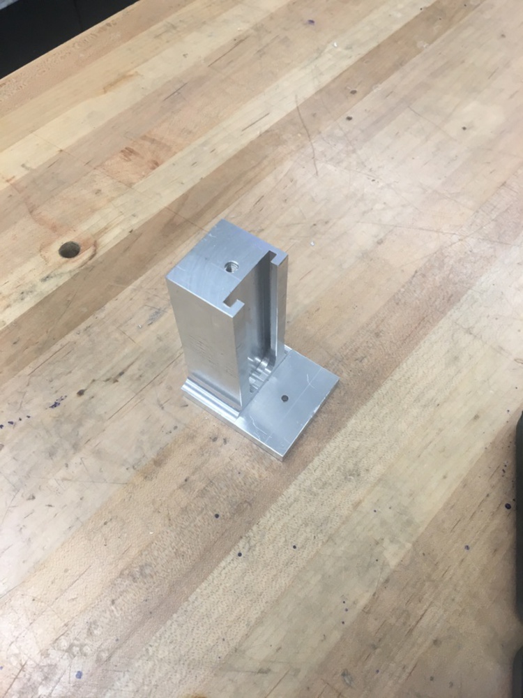
This base was by far the most complicated single part in my model, so I had to be very careful machining it. I made myself a drawing and annotated it with machining parameters. The cutter had to be positioned very precisely and the cutting operations had to happen in a specific order, and I managed to make it using only two setups in the mill. The final result was nearly perfect, and the acrylic slides very well in it.
The next obstacle was setting up the rod to move the Z axis. It was a difficult problem, since it needed to rotate but not move. After a lot of thought, I decided to drill and tap a 4-40 hole into the top of a thumb screw so I could constrain the thumb screw in he Z direction while still allowing it to rotate. That is what the hole in the bottom of the base is for. Once that was solved, all the mechanics were done.
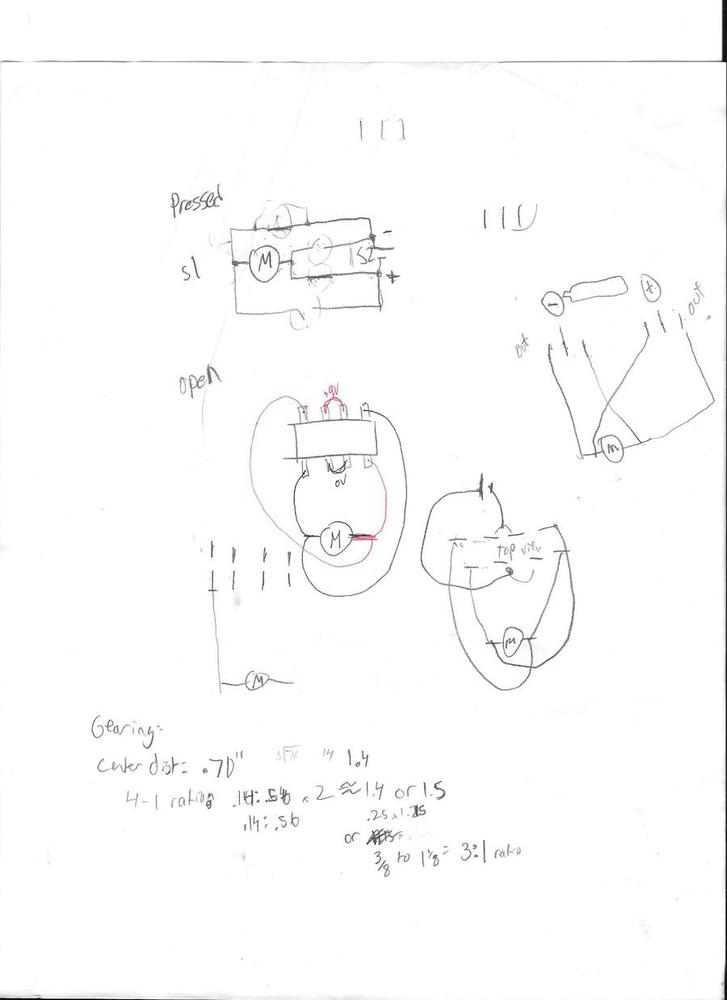
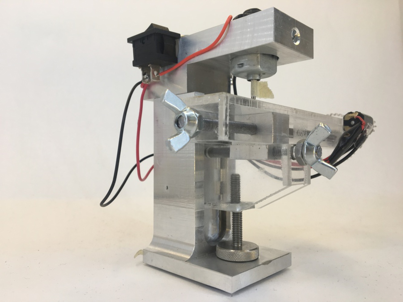
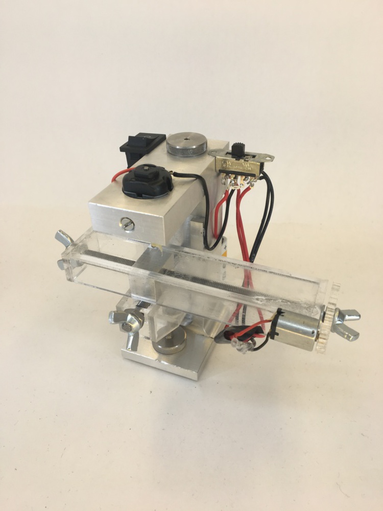
Once I had the mechanics down, I had to wire everything. I am not skilled with programming Arduinos, and I wanted to keep my wiring skills strong, so I decided to wire it all directly. I wanted to motorize the X axis since the 10-32 rods made it take forever to move the axes by hand and the X axis has a really big range of motion. I got a three position switch so I could have the motor move one direction, stop, and move the other direction without the aid of a controller. I also wanted the spindle to spin with a different switch, but not necessarily change direction. My messy wiring planning is below.
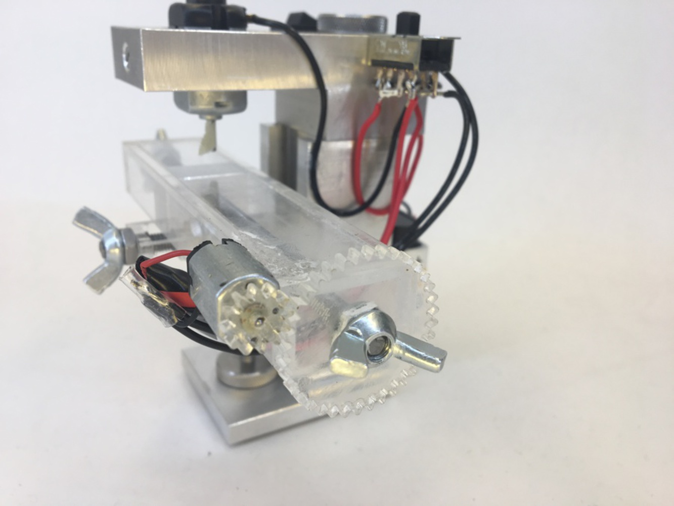
I did a lot of cutting wires, laying put lengths, soldering connections, and gluing wires down. It works perfectly! I was super proud that I got it working correctly and exactly how I envisioned it. Also seen at the bottom is my plan for gearing the axes. Since making a gearbox was not feasible with the time and space constraints, I decided to just direct drive a motor and gear it down so it could actually move. My rough gearing calculations told me that a 3:1 ratio was feasible, so I cut some gears out of acrylic, glued them onto the shafts, and did it.
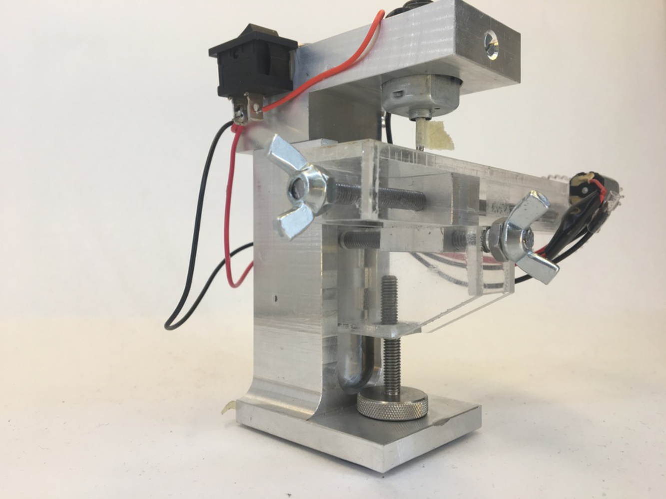
Overall, my mill works perfectly how I envisioned it, and I am so proud of the final result. It was a really fun project and really fun to make and test everything. Glamour shots and video are below. Full screen the videos to see them as they're meant to be seen: in a theater, on a big screen with surround sound surrounded by friends and family.
To make a desktop model of a Bridgeport milling machine