DIY Automotive Inspired Lamp
Made by Bryant Backus
Made by Bryant Backus
This project will utilize DIY fabrication methods to turn old car parts into a stylish lamp for the car enthusiast.
Created: April 29th, 2019
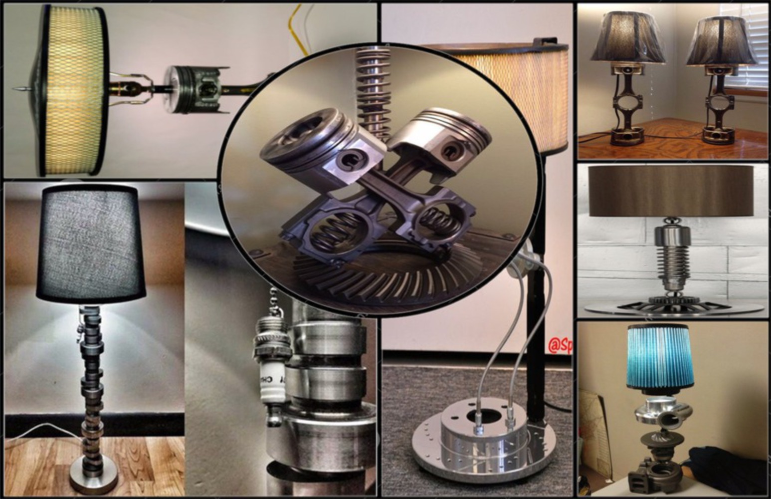
when coming up for inspiration for the lamp, I initially looked at other similarly themed lamps. I then made a mood board for lamp designs to try and create my own design. The mood board can be seen below.
After looking at lamp designs, I then thought about the customer and created a mood board for them. The board tried to depict the lives they live including hobbies, favorite shows and movies, fun activities they like, famous enthusiast icons, and other lifestyle elements. All of these were put into the mood board shown below.
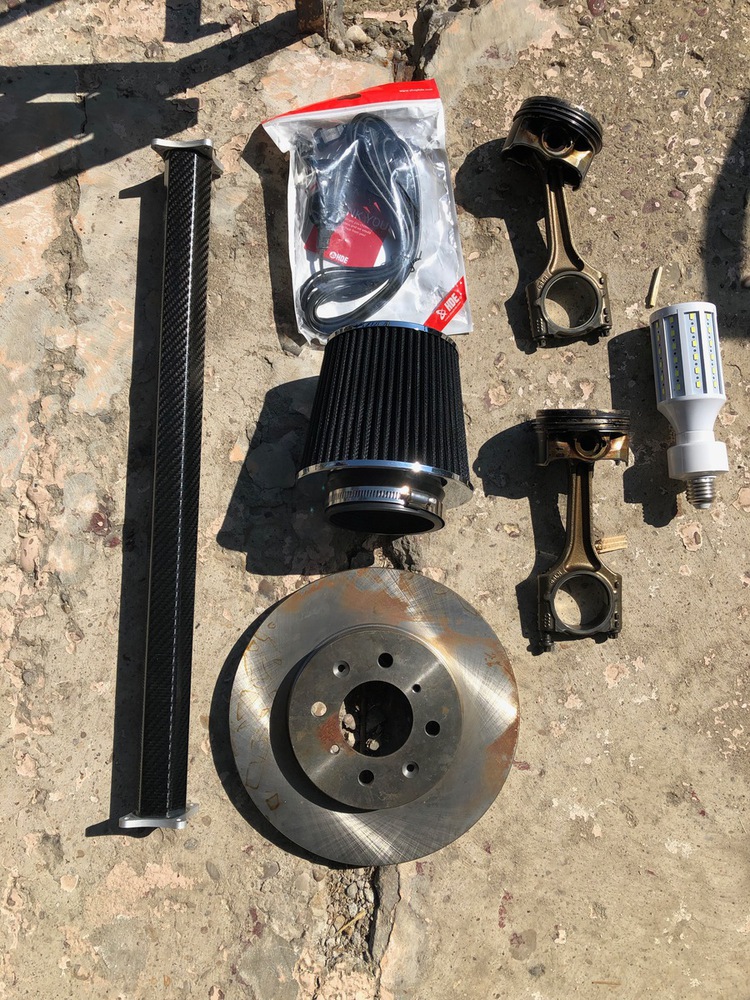
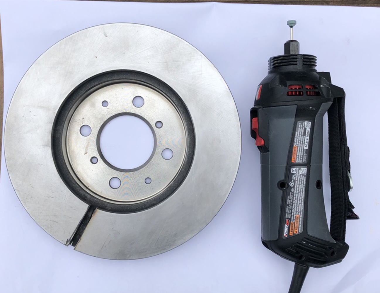
The next step was to source the necessary components in order to build the lamp. The list of components (which can be seen below) includes:
Additional parts created or added later on include:
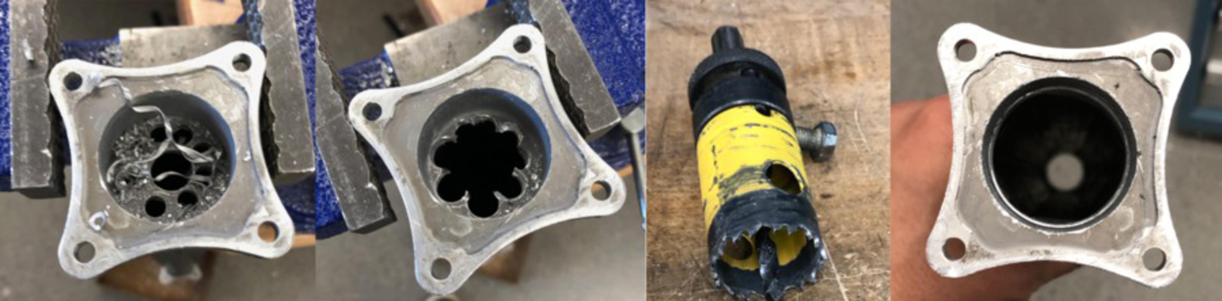
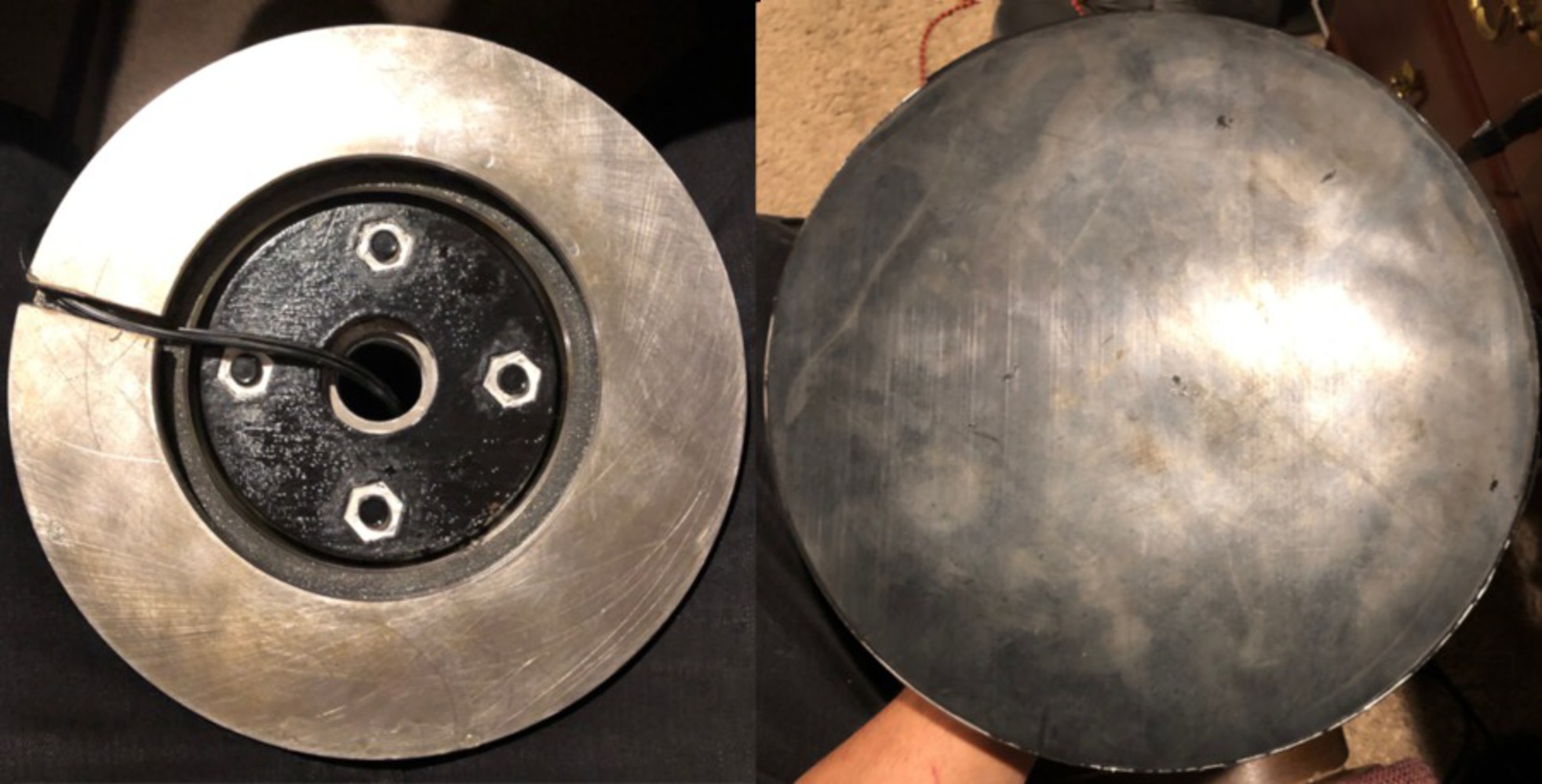
The first part of the process was to remove the material at the center on each end of the tube so that the power cord could pass through it. There was roughly a quarter inch wall on each side of the tube left from the machining process that created it. I began by drilling small holes around the perimeter of the tube inner diameter. I started with a small drill bit, and gradually increased the size until most of the material in the center of the tube was removed. I then planned to try and grind the rest down until the material was removed. There were problems with this as the grinding bits on the die grinder would pickup the material and it would get caught in the abrasive bit. This ruined the bit and made for a terrible process. Luckily, I found a hole saw with an OD that matched the ID of my tube. Using the hole saw, I was able to removed the remainder of the material in the tube. The progression of this can be seen in the collage below.
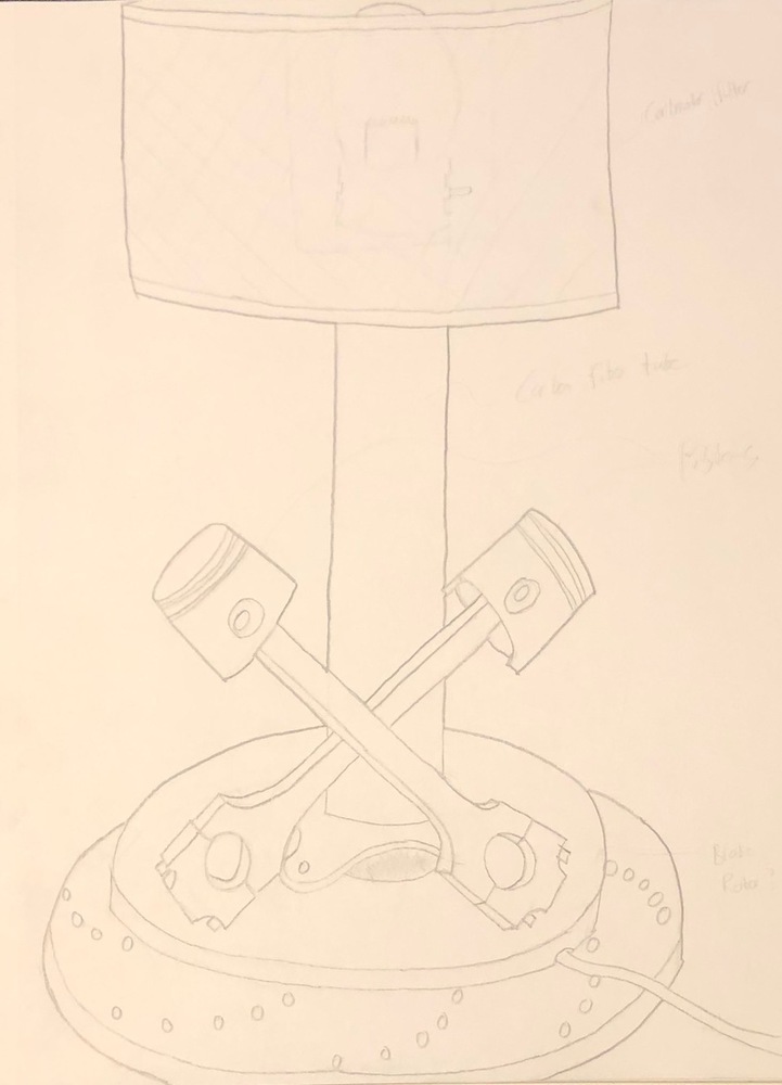
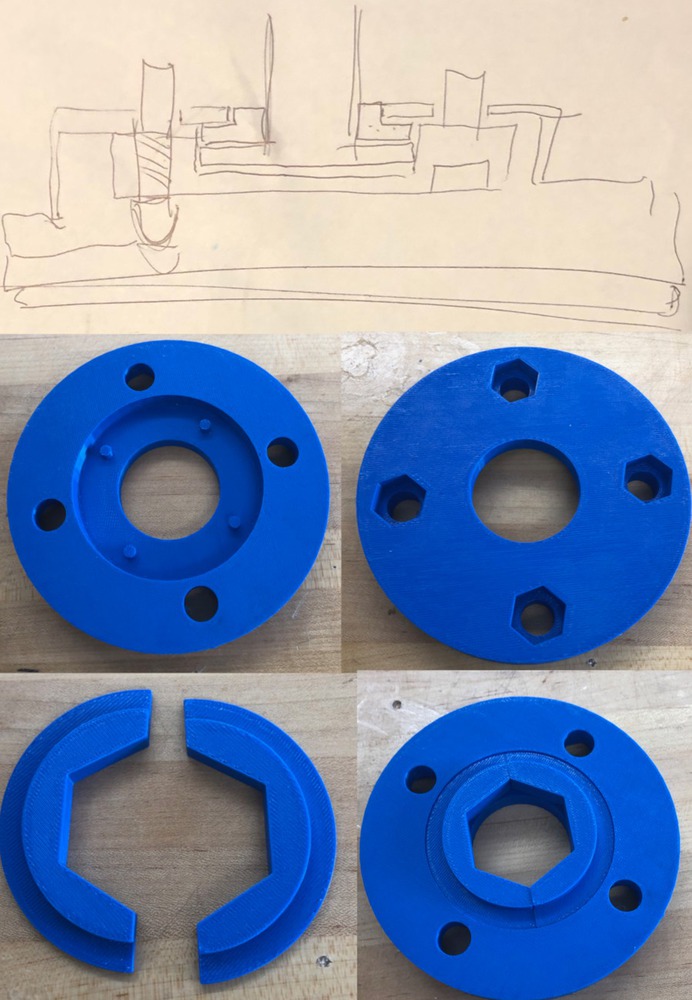
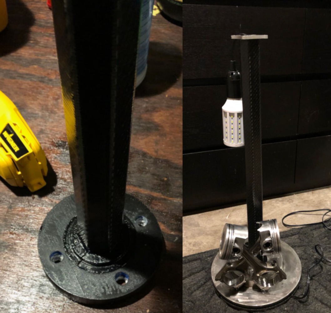
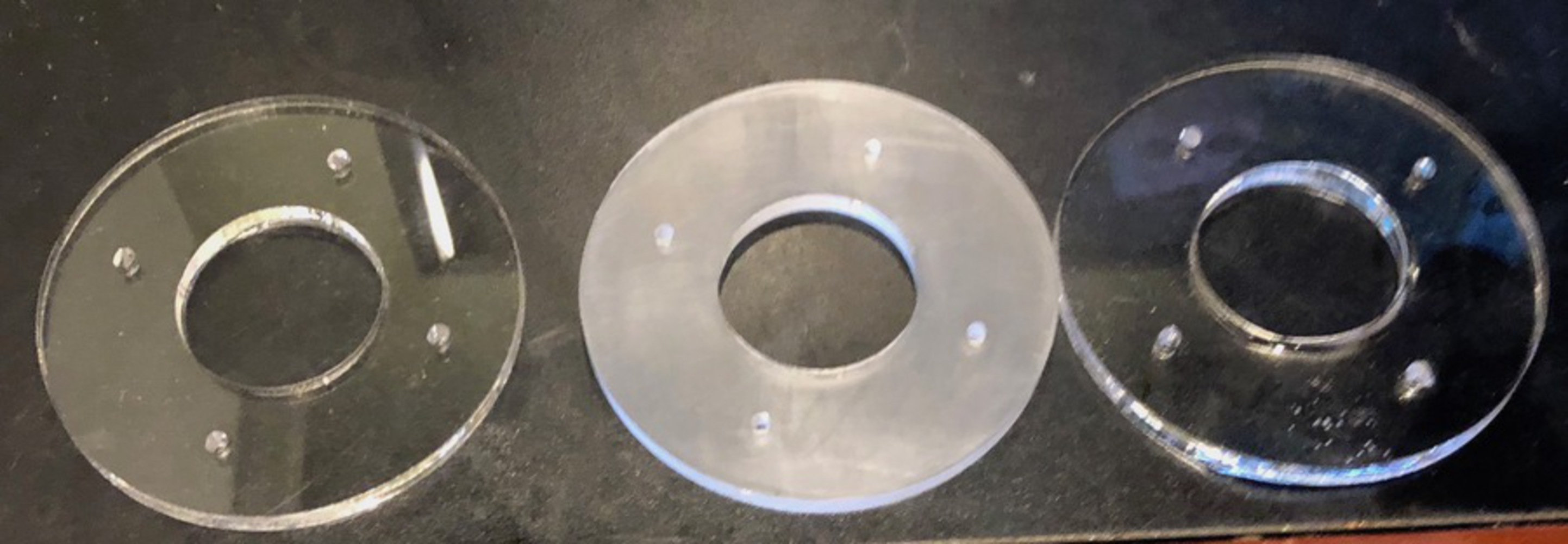
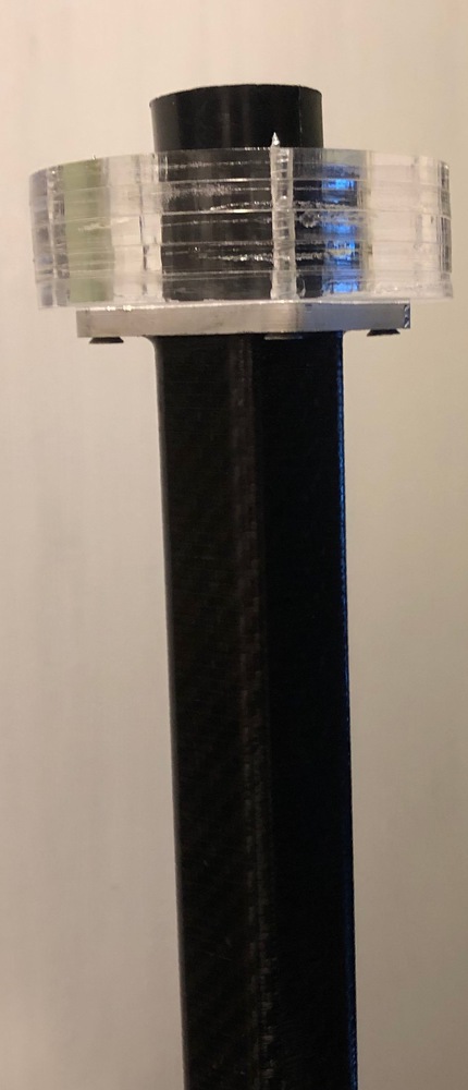
The next step was to create the connection point between the brake rotor (which is to be the base), and the carbon fiber tube (which is to be the stalk). After some sketch brainstorming with instructor Chris D'Eramo, we came up with a concept. It was to be a 3-piece component which I created in CAD and then had 3D printed. A picture of the sketches and the final product can be seen below:
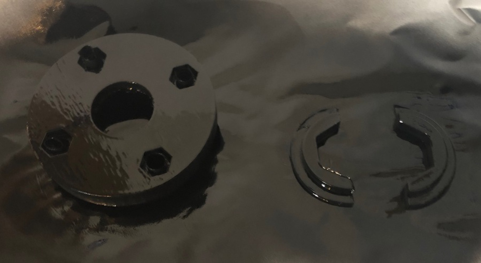
Part of this design included ordering 12x1.5 x 1inch lug bolts and M12 x 1.5 low profile nuts. the tube base would sit in the base piece, constrained by the four dowel pins. the two top pieces will sit around the tube and drop down into the base piece as seen in the bottom right. picture. The nuts will sit in their holes on the bottom and the lug bolts will pas through the rotor, then the 3D printed component and screw into the nuts. The component and the tube will then be constrained to the rotor via those bolts. Once tight the assembly will be lifted to the top of the rotor. These parts were then spray painted black to match the aesthetic of the lamp.
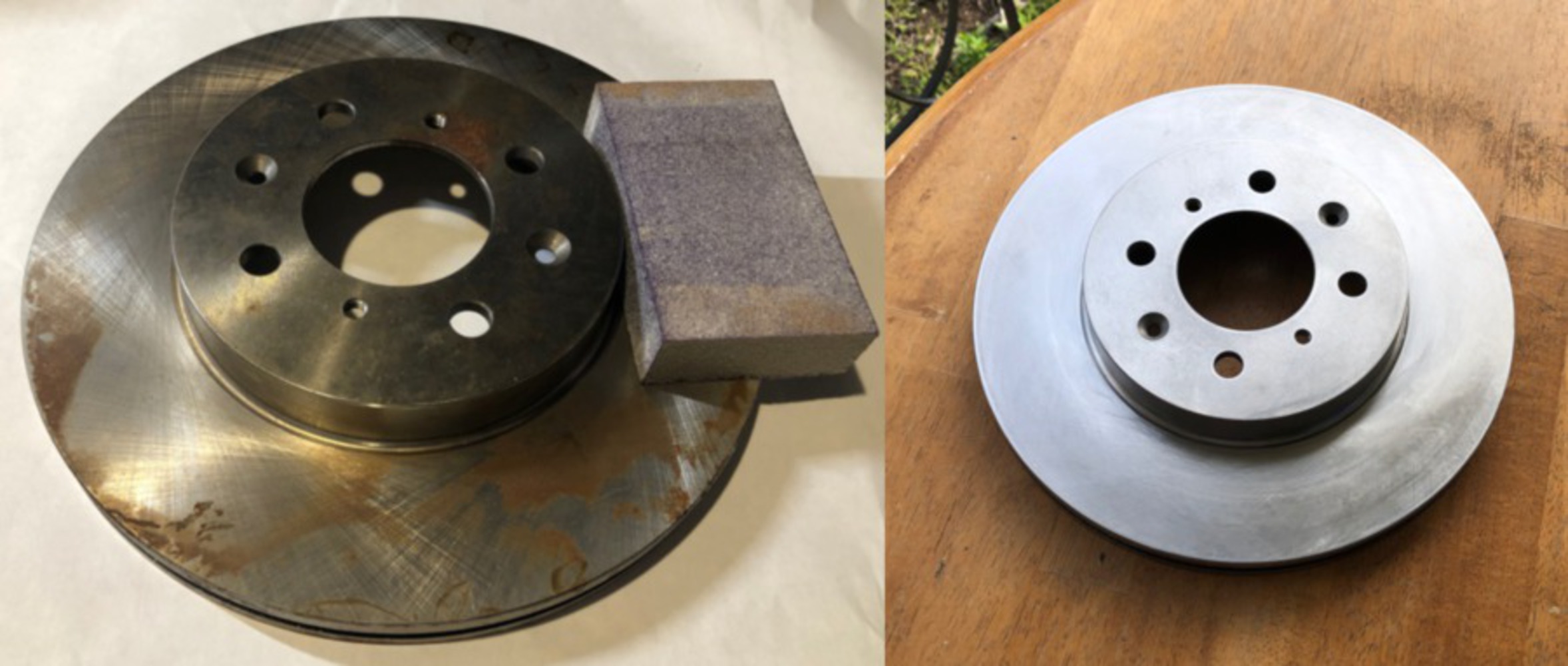
The next step was to use a grinder to cut a channel into the bottom of the rotor for the light cord to run out the bottom of the rotor. After cutting the channel, there were some sharp edges. these were taken care of using a Dremel to grind down the sharp edges. Once this was done, the rotor would be ready to weld the pistons onto.
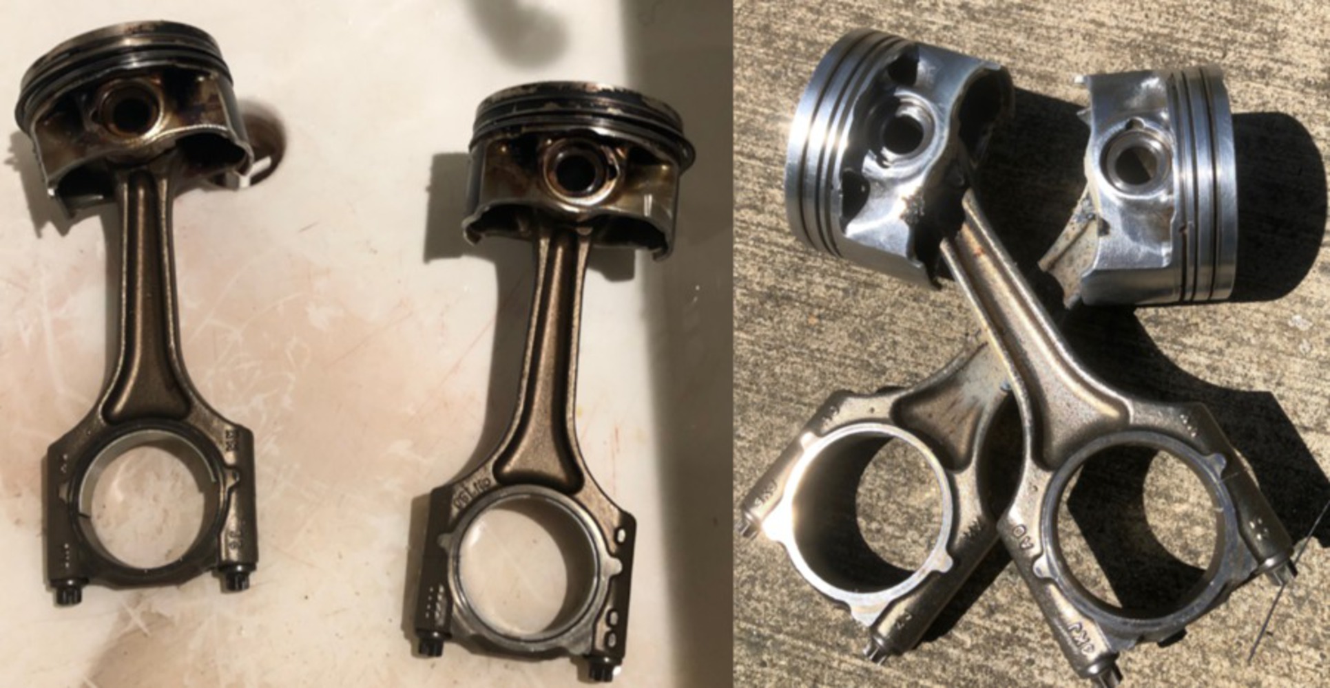
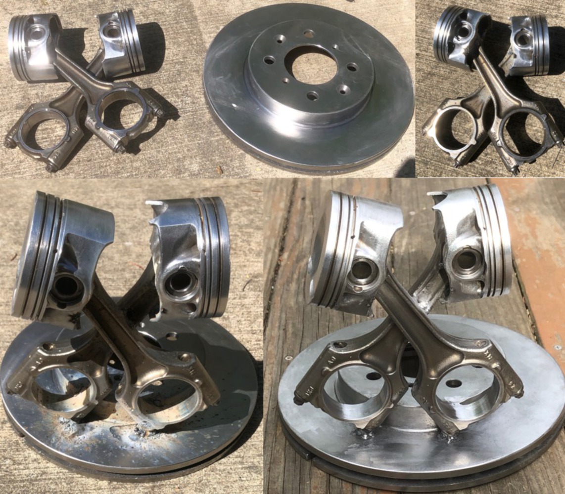
The first step in welding was to first weld the two pistons together crossed across each other. to keep the piston heads from moving about the rods, the heads were also tack welded in a couple places to keep them from moving. Once the pistons were welded together, they were propped in place on the rotor and then tack welded to the rotor. Once I was sure they were in a good position, I went over the tack welds and fully welded the pistons to the rotor.
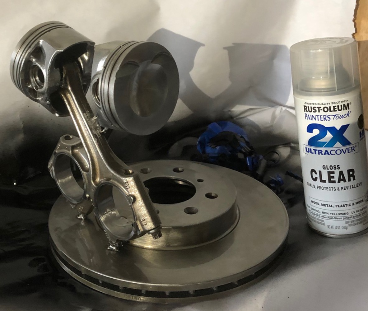
After letting the assembly cool off, I used a combination of chisel, oscillating multi-tool sander, hand sanding, Dremel, and wire brush to clean the slag from welding, metal spatter, and the welds themselves so that the rotor and pistons look clean. Photos from this process can be seen below.
Once the clear coat dried on the rotor, the carbon tube and 3D printed assembly was bolted to the rotor. Adhesive was applied to the bottom of the nuts so that they stay in their holes. The lug studs were then screwed into the nuts after passing through the rotor and assembly. The light pendant cord was then run through the tube and routed through the rotor and out.
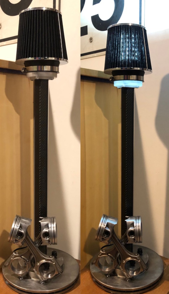
The next step was to create a surface that the air filter could clamp onto. I laser cut acrylic donut shapes with an OD that matched the ID of the air filter so it could clamp on and an ID that matched the OD of the lamp bulb socket. Now this piece could also be used to mount the bulb socket. I knew that I wanted a frosted surface finish on the exposed surfaces of the disk so I experimented with a couple methods. The first was sanding with high grit sand paper to mark the surface. Going back to the first project I was able to create a textured finish by heating the acrylic enough and so I also tried that. The heating up method did not work with clear acrylic. I imagine it was because of the dies in the black acrylic that allowed that to happen in project 1. Therefore I used the sanding method. to do this I wet sanded the side edges of the four disks to be used as well as the bottom surface of the bottom disk. First with 400 grit sandpaper, then with 600. This gave a nice frosted finish on the disks that didn't look completely scratched up.
Once the sanding was finished, the plates were stacked on top of the tube, and wood screws were screwed in from the bottom to clamp the plates to the mounting surface of the tube. Adhesive was then applied to the inner surfaces of the rings and the bulb socket was pushed down into the hole. At the same time, a silicon was injected into the rotor at the area the cord came out of. This would keep the cord from moving around and possibly getting damaged from abrasion.
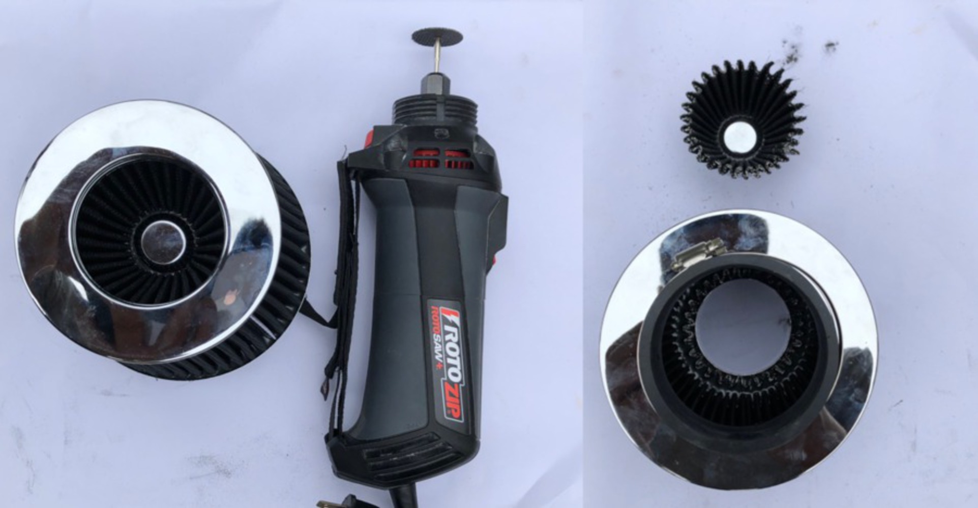
Once that was completed, the last step was to put the air filter on the top. The inner portion of the air filter was mostly empty except for a cone that came down from the end. In order to accommodate the length of the bulb and socket as well as allow light through the top, that would need to be cut out. A Dremel with a cutoff disk was used to cut that portion out.
94.606 KB · Download / View
Offers students hands-on experience in DIY product design and fabrication processes. Students work individually or in small groups to design customized and personalized products of their own and bu...more
This project will utilize DIY fabrication methods to turn old car parts into a stylish lamp for the car enthusiast.