Bridgequest
Made by yxuan, Shithe Al-Hasan and Tianlan Jiang
Made by yxuan, Shithe Al-Hasan and Tianlan Jiang
To create an interactive environment upon Schenley Bridge using IoT devices
Created: November 15th, 2019
General Idea and Purpose
Create an interactive game using IoT devices set up around the bridge.
Designing for the Environment and Community
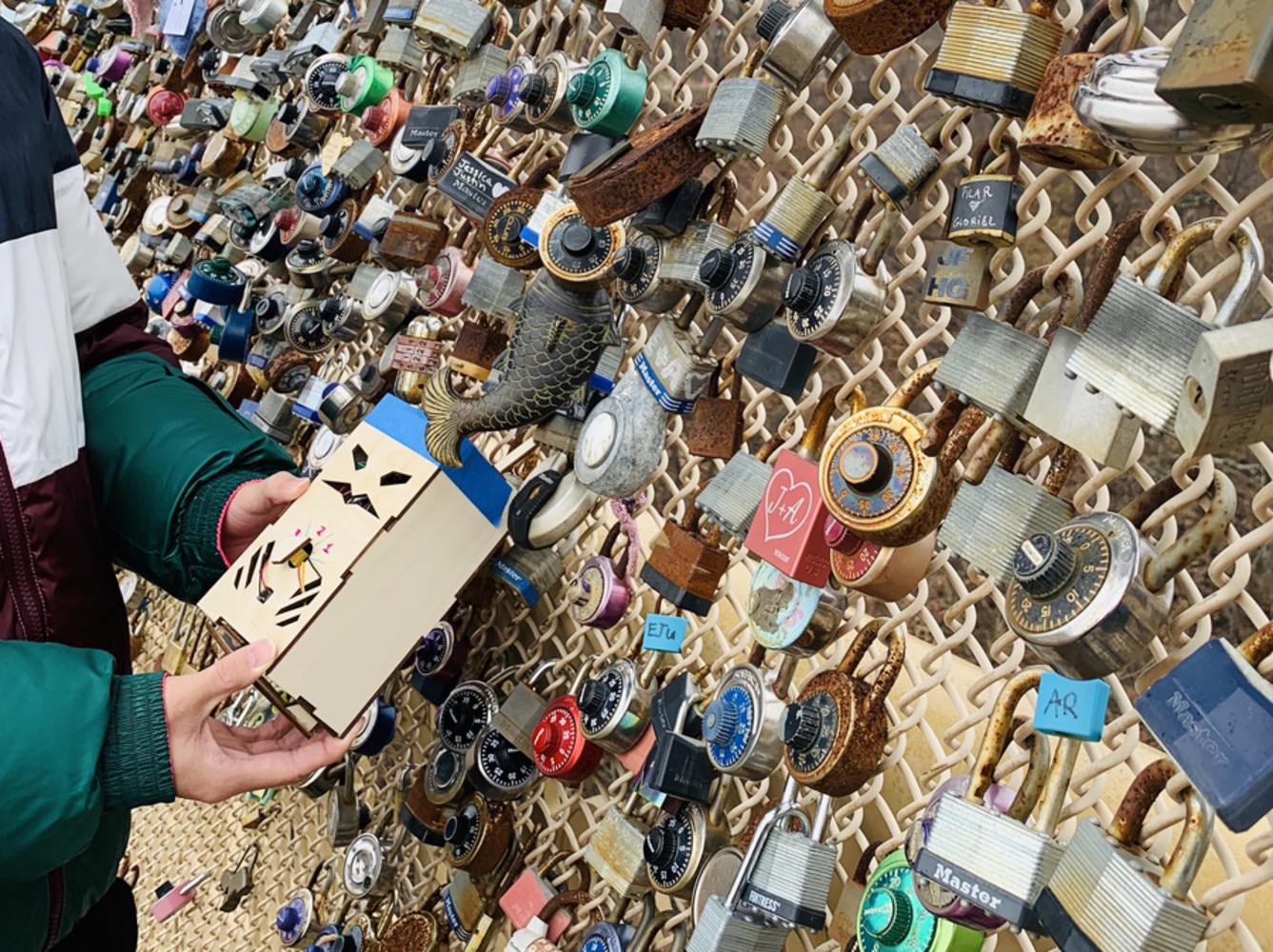
The game will lead pedestrians on the bridge to explore the history of the bridge and the unique locks on it. We will place a mysteriously fabricated lock with built-in speakers, potentiometer, amplifier, Particle Argon, lighting, and microservo. Audios play through our lock will instruct players to look around the environment to solve trivia quizzes to complete the game. Have Fun!
Final Iteration Detailed Description:
Our final iteration of Bridgequest features a single lock made out of plywood shell. On the front is a cartoonish face with glowing features, as well as a dial and a pushbutton. The lock is to hang from its shackle at the top. On the back is a speaker, and on the bottom is a panel connected to a servo that can flip down.
To start the game, a player would simply press the pushbutton, prompting an introductory voiceline and a scavenger hunt question. The voiceline asks the player to find a fish-shaped lock and count its fins, and return to the input the answer using the dial, which has three selections, and hitting the pushbutton again to submit the answer. Once the player inputs the answer, the lock will either glow red to indicate a wrong answer and repeat the question, or glow green and then purple, to indicate a correct answer and winning the game. The lock will congratulate the player and flip the bottom panel down to reveal a QR code.
Components
Initial Idea Description
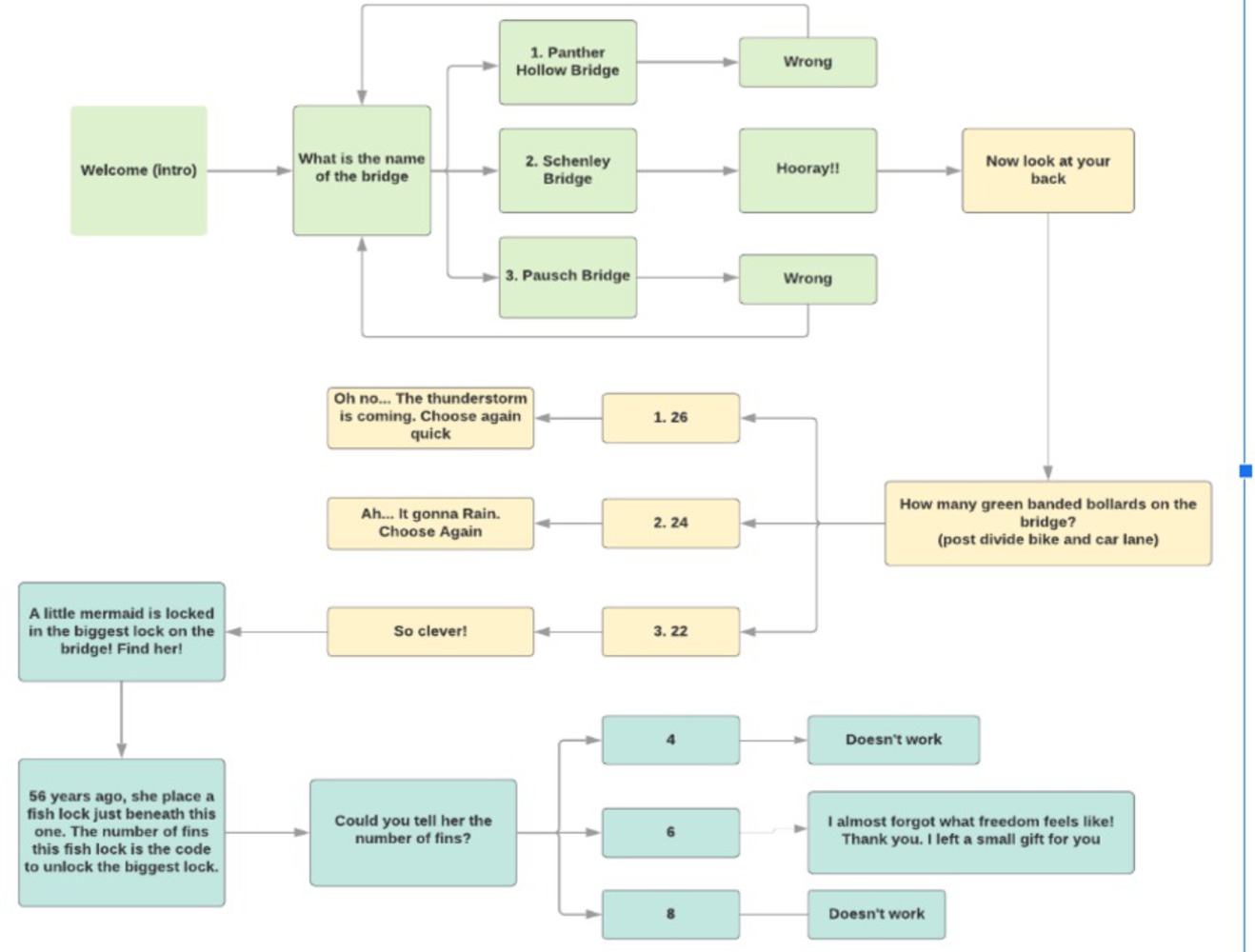
A game that features multiple custom smart locks that can communicate to players using audio and LED, and be interacted with using pushbuttons and potentiometers, through which a player finds clues to open 1 lock on the bridge. Unlocking the first lock sends players on missions to unlock 2nd lock and so in a sequence until the completion of the game. Locks may have multiple unlock codes which lead to different audio playing. Some unlock conditions may require people to cooperate. The missions are intended to lead players to interact with the bridge more.
For example, after receiving the proper input, the lock will tell the player to input the number of fence posts on the bridge into the next lock. At the end of all the missions, the final may physically “unlock” to allow the players to receive a prize, such as a QR code to a coupon.
Materials List and Costs
Project Components
Design Decisions:
1) Audio Instructions
Audio was chosen as the primary mode to convey information due to not needing to force the players to stop their visual enjoyment of the bridge and focus on small text. Whether the text is delivered via a screen on the lock, which would have limited space, or to the players' smartphones via QR code, the experience of enjoying the bridge itself would be diminished.
2) Type of Clues
The clues implemented were designed to encourage players to explore the bridge more, making note of its features and the surrounding view. They were also designed to be completed within a few minutes. Some of the clues we thought of were:
- How many bollards were there on the bridge?
- Which direction was Hammershlag Hall?
- When was the bridge constructed?
- How many locks are on a particular section of the fence?
3) Number of Clues
Initially, we wanted to implement multiple clues with multiple locks, taking players from lock to lock and different locations on the bridge. However, due to restrictions on the soundboard that required one digital pin from the Particle board to trigger each sound file, we were limited in the number of sound files we could use. An alternative we had was to use an Arduino as an intermediary between the soundboard and Particle; however this would have taken up too much space and power, so we decided to use only one clue.
In addition, during the demo, commentators suggested that players may not be willing to go to and from the lock multiple times, seeing it as a chore rather than a fun game, and would extend the game to beyond what players would have patience for. Instead, a singular, memorable clue would make the most of a 5-minute interaction. As result, the final Bridgequest contains only a singular question that we deemed most interesting.
4) Potientiometer and Pushbutton
The potentiometer was used for user input due to its general flexibility, having a wide range of readable values. The 0-4000 resistance range could be divided in which ever way that was convenient to the game. It was also similar to a traditional padlock. The pushbutton was important to give the premise of "submitting" an answer, and would also allow the first-time initiation of the game.
5) Reward
The reward is a panel attached to a servo that flips open on completion of the game. This gives the lock more animation, and intends to emulate magical locks of fantasy. The QR code is an easily accessible prize that removes the need to "restock" the device after use.
6) Glowing Spirit Aesthetic
The purpose of the face cutout on the front panel and the Neopixels inside is to attract players to stop by being visually interesting. By default the Neopixels glow blue, animating to green for correct answers and red for incorrect answers, allowing the device to stand out among the other locks on the fence.
7) Lock Size
The intent was for the lock to still fit in with the other locks hanging on the fence; however, the dimensions of the box were expanded to accommodate the electronics. It may be possible to decrease the size of the outer shell by phasing out use of jumper wires.
Prototype Iterations
1) Button and Potentiometer
Connected pushbutton and potentiometer to Particle on breadboard, allowing reading of their values.
2) General Game Structure
Used pushbutton and potentiometer to input into a general game structure with a logic and flow. Game records value of potentiometer every time the button is pressed and stores it. Game then compares all inputs to the correct answers; if one is incorrect, the game starts over. If all are correct, the game starts over.
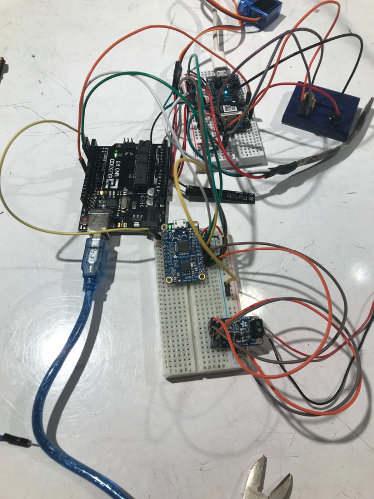
3) Soundboard Exploration
Exploration of the Adafruit Soundboard FX, the Adafruit Amplifier, and speakers. Created circuit on breadboard that allowed manual triggering of soundboard pins, playing the default example recordings.
4) Improved Game Input
Used Neopixels to indicate the correctness of the inputs from potentiometer and pushbutton. Implemented debounce to more reliably record inputs.
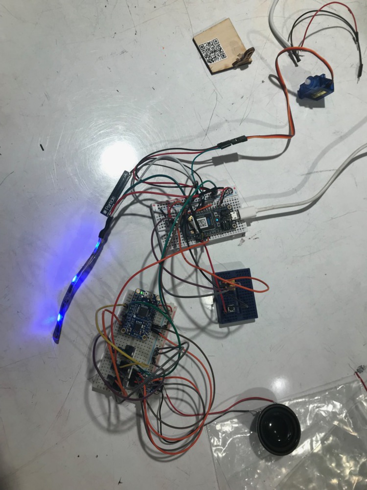
5) Soundboard Control
Exploration of soundboard control through Particle using Serial UART, and then Arduino. Implemented Particle GPIO control of Arduino, and Arduino Serial control of soundboard. Soundboard uploaded with custom voiceline files.
6) Lock Body Construction
Physical lock body modeled in Solidworks along with major components, converted into slotted/tabbed pieces and lasercut. First iteration too small, second iteration barely fit Improved Game Input prototype.
7) Demo
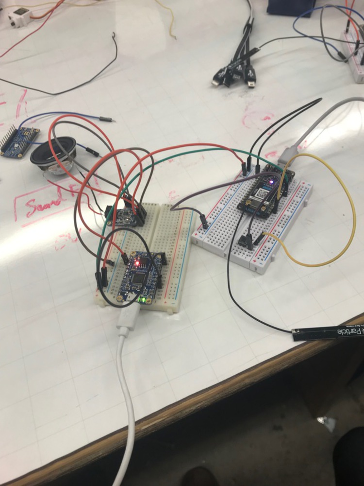
Lock separated into two components, each with own Particle controller: Input using pushbutton and potentiometer with Neopixel, and output using Arduino to control soundboard. Arduino could be made to play 1 track on soundboard.
8) Soundboard and Input Combination
Utilized instructor suggestion to use only one clue to simplify implementation. Used Particle GPIO pins to trigger soundboard pins using transistors. All power routed through Particle, to mobile power pack. Reward panel servo added.
9) Final Iteration
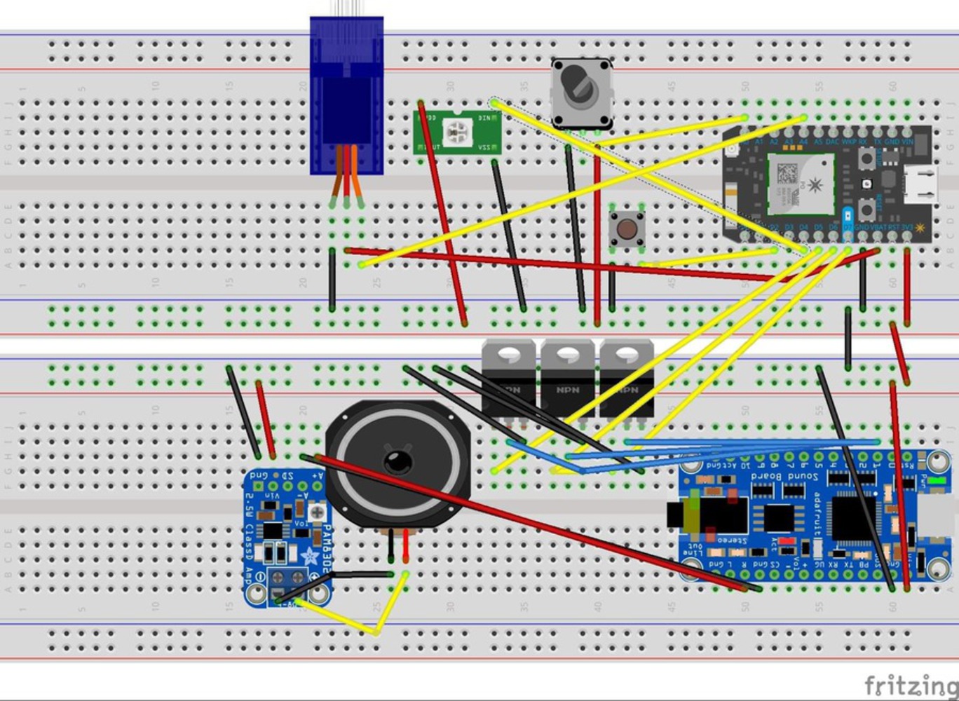
Increased lock body dimensions by 50%. Glued small breadboard mounted with pushbutton and potentiometer to front plate of lock body. All electronics: 2 breadboard circuits, with Particle and soundboard respectively, one speaker, one servo, 3 pixels of Neopixel, and one mobile power pack, fit inside lock body.
// This #include statement was automatically added by the Particle IDE.
#include <neopixel.h>

// This #include statement was automatically added by the Particle IDE.
#include <neopixel.h>


#define PIXEL_PIN D4
#define PIXEL_COUNT 17
#define PIXEL_TYPE WS2812

Adafruit_NeoPixel strip = Adafruit_NeoPixel(PIXEL_COUNT, PIXEL_PIN, PIXEL_TYPE);

int potPin = A0;
int buttonPin = D2;
int potReading = 0;

int servoPin = A4;
Servo myServo;
int servoPos = 0;
int speakerPin = D0;

void processanswers(void);

//int number_of_questions = 1;

bool correctness[] = {false};
int correctanswers[] = {1};
int playeranswers[1];

int count = 0;
bool first_encounter = true;

int buttonState;
long lastDebounceTime = 0;
long debounceDelay = 2500;
long gamewait = 300000;

int soundpin[] = {D5,D6,D7};

int pin4 = D8;

int R = 0;
int G = 0;
int B = 255;


void setup() {

strip.begin();
strip.show();
setcolor();

pinMode(D5, OUTPUT);
pinMode(D6, OUTPUT);
pinMode(D7, OUTPUT);

digitalWrite(soundpin[0], LOW);
digitalWrite(soundpin[1], LOW);
digitalWrite(soundpin[2], LOW);

pinMode( buttonPin , INPUT_PULLUP);

myServo.attach(servoPin);
myServo.write(0);

Particle.variable("pot",potReading);
Particle.variable("count",count);

}

void loop() {

buttonState = digitalRead(buttonPin);

potReading = analogRead(potPin);

    if ( (millis() - lastDebounceTime) > debounceDelay) {
        if (buttonState == LOW)  {
            lastDebounceTime = millis();

            processanswers();
        }
    }


delay(10);
}


void processanswers(){


    playeranswers[count] = (int)(potReading/1000);

    if (playeranswers[count] == correctanswers[count] && !first_encounter){
        correctness[count] = true;
    }

    checkanswers();
}


void checkanswers(){

   if (first_encounter){
    R = 0;
    G = 255;
    B = 0;

    setcolor();

    voiceline(0);
    delay(12000);

    voiceline(1);
    setcolor();

    first_encounter = false;
   }

   else {
   if (correctness[count] == false) {
        R = 255;
        G = 0;
        B = 0;

        setcolor();
        delay(10);
        setcolor();
        voiceline(1);

        count = 0;

   }

   else if (correctness[count] == true){
        R = 0;
        G = 255;
        B = 0;
        setcolor();
        delay(10);
        setcolor();
        count ++;
   }

   if (count == 1){
    R = 255;
    G = 0;
    B = 255;


    setcolor();

    voiceline(2);

    delay(5000);
    myServo.write(90);
    delay(20000);
    myServo.write(0);

    setcolor();

    count = 0;
    first_encounter = true;

    for(int i = 0; i <= 1; i++){
    correctness[i] = false;
        }

        }
    }
}


void setcolor(){

uint16_t j;
uint32_t c = strip.Color(R, G, B);

for(j=0; j< strip.numPixels(); j++){
    strip.setPixelColor(j, c );
    	strip.show();
  }

 if ((R == 255) or (G == 255)) {
      delay(500);
      R = 0;
      G = 0;
      B = 255;
  }

}

void voiceline(int voicenumber){

        digitalWrite(soundpin[voicenumber], HIGH);
        delay(1000);
        digitalWrite(soundpin[voicenumber],LOW);

}Thermostats, locks, power sockets, and lights are all being imbued with smarts making them increasingly aware and responsive to their environment and users. This course will chart the emergence of ...more
To create an interactive environment upon Schenley Bridge using IoT devices